| Tweet |

Custom Search
|
|
 
|
||
|
Water-Jacket
Liners A cylinder sleeve of the water-jacket type has its own coolant jacket as an integral part of the liner assembly. The jacket may be brazed on (fig. 3-12), cast on (fig. 3-13), shrunk on, or sealed on (fig. 3-14) the liner. The liner shown in figure 3-12 is a brazed-on jacket type with a separate water jacket brazed onto the cylinder liner. In this type of liner, the inlet water circulates around the bottom of the liner. The water then progresses upward and discharges through drilled passages at the top of the liner into the cylinder head. Seals are placed around each drilled water passage so that the water passages will be watertight when the cylinder head is installed. The water-jacket liner shown in figure 3-13 is of the cast-on jacket type. The water jacket is formed by the inner and outer walls of the liner. Ports divide the water space into lower and upper spaces, which are connected by vertical passages between the ports. The flow path for cooling in this liner is basically the same as in the brazed type of liner.
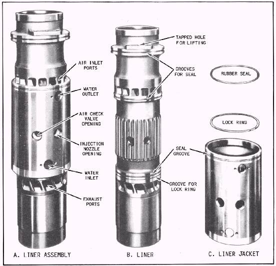
Figure 3-14.A water-jacket cylinder liner assembly with a sealed-on jacket. The water-jacket liner shown in figure 3-14 (view A) is of the sealed-on jacket type. This assembly consists of two components, the liner (view B) and the liner jacket (view C). The cylinder liner is sealed within the liner jacket by upper and lower O-rings. The liner (view B) is constructed with vertical ribs in the middle, between the inlet and exhaust ports. These ribs direct the water travel upward, absorbing heat from this part of the cylinder. Midway up the liner, openings are provided for the two injection nozzles, an air start check valve, and a cylinder relief valve. Additional information on liners can be found in Naval Ships Technical Manual, chapter 233. |
 |
|
|
||