| Tweet |

Custom Search
|
|
 
|
||
|
Methods
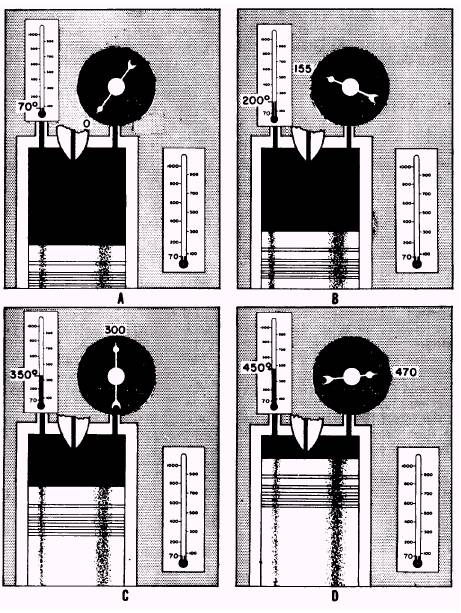
of Ignition When the gases within a cylinder are compressed, the temperature of the confined gases rises. As the compression increases, the temperature rises. In a gasoline engine, the compression temperature is always lower than the point at which the fuel will ignite spontaneously. Thus, the heat required to ignite the fuel must come from an external source (spark plug). This method is referred to as SPARK IGNITION. On the other hand, the compression temperature in a diesel engine is far above the ignition point of the fuel oil. Therefore, ignition of the fuel takes place as a result of heat generated by compression of the air within the cylinder, an action referred to as COMPRESSION IGNITION. The difference in the methods of ignition indicates that there is a basic difference in the combustion cycles upon which diesel and gasoline engines operate. The difference involves the behavior of the combustion gases under varying conditions of pressure, tem-perature, and volume. Since this is so, you should be familiar with the relationship of these factors before considering the combustion cycles individually. (The basic laws and processes involved in a volume, temperature, and pres-sure relationship are discussed under the proper-ties of gases in Fireman, NAVEDTRA 10520-H.) You should also be aware that compression ratio (clearance volume) refers to the comparison between the volume above the piston at BDC to the volume above the piston at TDC. Relationship of Temperature, Pressure, and Volume The relationship of temperature, pressure, and volume as found in an engine can be illustrated by a description of what takes place in a cylinder that is fitted with a reciprocating piston. Follow views A through D in figure 2-4. Note the instruments that indicate the pressure within the cylinder and that the temperature both inside and outside the cylinder is approximately 70F. Assume the cylinder is an airtight container, as it is in our example. Now compare views A and B of figure 2-4. If a force pushes the piston toward the top of the cylinder, the entrapped charge is compressed. In views B and C, the compression progresses. The VOLUME of the air DE-CREASES, the PRESSURE INCREASES, and the TEMPERATURE RISES. These changing conditions continue as the piston moves. When the piston nears TDC in view D, there has been a marked decrease in volume. Also, both pressure and temperature are much greater than at the beginning of compression. Notice that the pressure has gone from 0 psi to 470 psi and
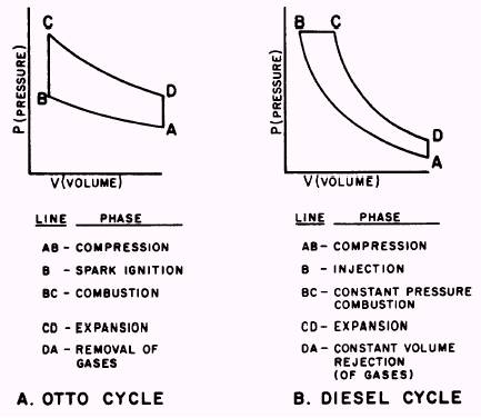
Figure 2-4.Volume, temperature, and pressure relationships in a cylinder. the temperature has increased from 70F to approximately 450F. These changing conditions indicate that mechanical energy, in the form of force applied to the piston, has been transformed into heat energy in the compressed air. The temperature of the air has been raised sufficiently to cause ignition of the fuel that is injected into the cylinder. Further changes take place after ignition. Since ignition occurs shortly before TDC, there is little change in volume until the piston passes TDC. However, there is a sharp increase in both pressure and temperature shortly after ignition takes place. The increased pressure forces the piston downward. As the piston moves downward, the gases expand (increase in volume), and pressure and temperature decrease rapidly. These changes in volume, pressure, and temperature are representative of the changing conditions in the cylinder of a diesel engine. In comparison with the requirement of a diesel engine, a gasoline engine needs a lower compres-sion ratio and lower combustion chamber temper-atures. The reason for this is that the heat of compression of a diesel engine would ignite a gasoline and air mixture before the piston could approach the top of its stroke. This pre-ignition would tend to drive the piston back down the cylinder and place an excessive, damaging strain on the engine. As a rule, gasoline engines use compression ratios under 10:1. It is the electric spark that causes ignition of the fuel to occur. The changes in volume and pressure in an engine cylinder can be illustrated by diagrams similar to those shown in figure 2-5. Such diagrams are made by devices that measure and record the pressures at various piston positions during a cycle of engine operation. Diagrams, such as these, that show the relationship between pressures and corresponding piston positions are called PRESSURE-VOLUME DIAGRAMS or INDICATOR CARDS. On diagrams that provide a graphic representation of cylinder pressure as related to volume, the vertical line P on the diagram represents pressure and the horizontal line V represents volume. (Refer to fig. 2-5.) When a diagram is used as an indicator card, the pressure line is marked off in inches. Thus, the volume line can be used to show the length of the piston stroke
Figure 2-5.Pressure-volume diagrams for theoretical combustion cycles. that is proportional to volume. The distance between adjacent letters on each of the diagrams (views A and B of fig. 2-5) represents an event of a combustion cycle. A combustion cycle includes compression of air, burning of the charge, expansion of gases, and removal of gases. The diagrams shown in figure 2-5 provide a means by which the Otto and diesel combustion cycles can be compared. Referring to the diagrams as we discuss these combustion cycles will help you to identify the principal differences between these cycles. The diagrams shown are theoretical pressure-volume diagrams. Diagrams representing conditions in operating engines will be given later. |
 |
|
|
||