| Tweet |

Custom Search
|
|
 
|
||
|
INSPECTING, MAINTAINING, AND REPLACING PISTON RINGS
AND PISTONS
The following paragraphs are general procedures for inspections, maintenance, and replacement of piston rings and pistons. You must consult the manufacturers technical manual for specific instructions. PISTON RINGS Over a period of time all piston rings wear. Some stick and may even break. While you may be able to free stuck rings and make them serviceable, you must replace excessively worn or broken rings with new ones. The installation of a new set of rings in an engine requires great care. Most of the damage that is done occurs when the rings are being placed in the grooves of a piston or when the piston is being inserted into the cylinder bore. Be very careful when you remove the piston and connecting rod from the cylinder. In most engines, you should not remove a piston from a cylinder until you have scraped the cylinder surface above the ring travel area. In addition to removing all carbon, you must remove any appreciable ridge before removing the piston. Do not remove a ridge by grinding, as this will allow small abrasive particles from the stone to enter the engine. Use a metal scraper and place a cloth in the cylinder to catch all metal cuttings. You can usually scrape enough from the lip of a cylinder to allow the piston assembly to slide out of the liner. After removing the piston, you can make a more detailed inspection of the ridge. Finish scraping the remaining ridge, but be careful not to go too deep. Finish the surface with a handstone. For large ridges, you may need to remove the liner and use a small power grinder. With the piston and connecting rod removed, check the condition and wear of the piston pin bushing, both in the piston and in the connecting rod. The best way to remove and install piston rings is with a tool similar to that shown in figure 3-19. These tools generally have a device that limits the amount the ring can be spread and prevents the rings from being deformed or broken. A ring that is securely stuck in the groove will require additional work. You may need to soak the piston
Figure 3-19.Piston ring tools used for removal or installation. overnight in an approved cleaning solvent or in diesel oil. If soaking does not free the ring, you must drive it out with a brass drift. The end of the drift should be shaped and ground to permit its use without damage to the lands. After removing the rings, thoroughly clean the piston with special attention to the ring grooves. (Diesel oil or kerosene are satisfactory cleaning agents.) In addition, you may need to clean excessive deposits from the oil return holes in the bottom of the oil control ring grooves with a twist drill of a diameter corresponding to the original size of the holes. Make another complete inspection after cleaning the piston. Check all parts for any defects that could require replacement of the piston. Give particular attention to the ring grooves, especially if the pistons have been in service for a long period of time. A certain amount of enlargement of the width of the grooves is normal, and SHOULDERING of the groove may occur. Shouldering, as illustrated in figure 3-20, results from the hammering out motion of the rings. The radial depth of thickness of the ring is much less than the groove depth, and while the ring wears away an amount of metal corresponding to its own width, the metal at the bottom of the groove remains unchanged. Shouldering
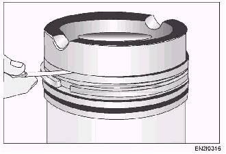
Figure 3-20.Ring groove shoulders due to wear. usually requires replacement of the piston since the shoulders prevent the proper fitting of new rings. After determining that a piston isserviceable, inspect the rings carefully todetermine whether they can be reused. If they do not meet specifications, youmust install new rings. When installing rings, measure the gap with a feeler gauge. To measure the gap, place the new rings inside the cylinder liner (fig. 3-21, view A) or in a ring gauge. When the gap is measured with the ring in the liner (fig. 3-21,view B), two measurements are necessaryone just below the upper limit of ring travel, and the other within the lower limit of travel. These measurements are necessary because the liner may have a slight amount of taper caused by wear. The ring gap must be within the limits specified in the manufacturers technical manual. If the gap of a new ring is less than specified, file the ends of the ring with a straight-cut mill file to obtain the proper gap. If the gap is more than specified, install oversized rings. To measure the ring gap of used rings, hold the rings in place on the piston with a ring compressing tool (fig. 3-22). But before you measure the ring gap with the ring on the piston, first measure the piston for wear and out-of-roundness. After ensuring the proper gap clearance, you can reinstall the piston pin and connecting rod. During reassembly and installation of a piston and connecting rod assembly, be sure that all parts are well lubricated. Install the rings on the piston with tools similar to those used for ring removal. When installing piston rings, spread them as little as possible to avoid breaking the rings. Insert the lowest ring first. When all the rings have
Figure 3-21.A. Leveling a piston ring. B. Measuring ring gap clearance in a cylinder bore.
Figure 3-22.Checking ring gap clearance. been installed, check the ring-to-land clearance. (See fig. 3-23.) If the clearance is too small, the ring may bind or seize, allowing improper sealing and blowby to occur. If the clearance is excessive, the ring may flutter and break itself or the piston land. After you have properly installed all the rings, coat the entire assembly with oil, then insert it into the cylinder bore. Position the rings so the gap of each successive ring is on an alternate side and the gaps are in line with the piston pin bosses. On large engines, use a chain fall to hold the piston assembly in position as you lower it into the cylinder. (See fig. 3-24.)
Figure 3-23.Checking ring groove side clearance.
Figure 3-24.Installing a piston in a cylinder bore with a funnel-type ring compressor. When a piston is being inserted into a cylinder, the piston rings must be compressed evenly. Special funnel-type tools, similar to the one shown in figure 3-24 are usually provided for this purpose. Another type of ring compressing tool is a steel band that can be placed around the ring and tightened. |
 |
|
|
||