Custom Search
|
|
 
|
||
|
Capacitor Dielectric Absorption Dielectric absorption is the inability of a capacitor to discharge completely to zero. This is sometimes called battery action or capacitor memory and occurs because the dielectric of the capacitor retains a charge. All capacitors have some dielectric absorption, but electrolytic capacitors have the highest amount, and it will often affect circuit operation if it becomes excessive. You can check electrolytics for dielectric absorption during the normal test for capacitor value and leakage by simply rechecking the value of the capacitor after the leakage test in the following manner: 1. Connect the capacitor to the test leads and test for the capacitor value in the normal manner. Note the value of the capacitor. 2. Test the capacitor for leakage at the rated working voltage of the capacitor. Allow the leakage current shown on the display to drop to the maximum allowable leakage or below, as shown on the leakage chart in figures 4-31 or 4-32, depending on the type of capacitor. 3. Release the LEAKAGE button and allow the display to drop to 000. Then immediately depress the VALUE button and note the capacitor reading. a. If the capacity reading is within 5 percent of the original value and the reading increases slowly upward toward the original value, or if there is no difference in the readings, the capacitor has little dielectric absorption and is good. b. If the value reading difference is greater than 5 percent but less than 15 percent, the capacitor may require reforming as described later. Some of the dielectric oxide has deteriorated, and reforming the electrolytic may bring it back to a useful life. Recheck for dielectric absorption after attempting to reform the capacitor. c. If the value reading difference is greater than 15 percent and the reading changes upward rapidly toward the original value, the capacitor has excessive dielectric absorption. Electrolytic capacitors exhibiting this much dielectric absorption may be reformed in some cases. If the capacitor exhibits similar dielectric absorption after reforming has been attempted, it should be replaced; otherwise, it will give trouble in the circuit. NOTE: If a mica or film type of capacitor shows any dielectric absorption, it can be considered bad and should be replaced. Reforming of Electrolytic Capacitors Aluminum electrolytics will often show low value or high leakage if they have been sitting on a shelf for a long period of time. Generally, any aluminum electrolytic capacitor sitting on the shelf for over 1 year will show one or both of these characteristics. This is caused by a loss of some of the oxide coating that forms the dielectric of the capacitor. In many cases, the oxide coating may be reformed with the application of a dc voltage for a period of time. The capacitorinductor analyzer can reform the dielectric material by using the same dc power supply that is used for leakage testing. Reforming may require more than an hour before the capacitor returns to its normal condition. A TEST BUTTON HOLD-DOWN ROD is included with the analyzer to hold the LEAKAGE button down for reforming electrolytics. 1. Connect the electrolytic to be reformed to the test leads observing polarity. 2. Select the proper voltage with the APPLIED VOLTAGE switch. 3. Depress the LEAKAGE button and, while holding the button in, place the hold-down rod on the button. Bring the meter carrying handle to the front of the meter and wedge the hold-down rod between the handle and the LEAKAGE button so that the rod holds the button depressed (fig. 4-33). CAUTION This method of holding the LEAKAGE button in provides a greater degree of safety than a "latching" type of switch. Always observe extreme caution when you see the handle in front of the switches, as this will tell you voltage is being applied to the test leads and capacitor. Never attempt to operate any other function push buttons when the hold-down rod is being used. 4. After the capacitor has been reformed for at least 1 hour, let it discharge and sit for about 30 minutes. Then recheck the value and the leakage to see if the reforming process has improved the capacitor.
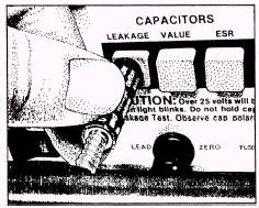
Figure 4-33.\Application of the hold-down rod. These are just a few of the tests that can be performed with a capacitor analyzer. Consult the operator's manual for the 'test equipment that you are operating for additional information. |
 |
|
|
||