Custom Search
|
|
 
|
||
|
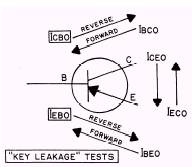
Transistor Leakage Leakage in a transistor can shunt signals or change bias voltages and upset circuit operation even though the transistor has gain. Transistor leakage should be checked whenever circuit troubleshooting indicates improper bias voltages even though the transistor has gain. There are six possible leakage paths in a transistor (fig. 4-23). Collector/base (ICBO) and emitter/base (IEBO) leakage paths are the two key leakage paths that most often upset circuit operation. The tester will read all six paths if you rotate the PERMUTATOR SWITCH through all six positions indicated for the polarity of the device under the test. KEY LEAKAGE TEST Leakage tests should be done out of circuit, since the associated components of the circuit may cause false leakage readings. To test for key leakage: 1. Perform the transistor gain test as described previously. Note the two positions that indicate GOOD gain on this test. 2. Depress the LEAKAGE push button with the PERMUTATOR SWITCH in either of the transistor gain positions and read the leakage on the lower (ICBO/IGSS) scale of the meter. 3. Switch the PERMUTATOR SWITCH to the other position that gave the transistor gain test. Again depress the leakage button and read the leakage on the meter. Refer to table 4-1 for typical leakage limits. Rectifier Diode Testing The transistor tester can check the front-toback current leakage of a diode. Since the resulting readings are given in microamperes, the results may be compared to a specification (spec) sheet to determine if the diode is within specs. The
Figure 4-23.\Leakage paths for a PNP transistor. Table 4-1.\Transistor Leakage Chart
test will also determine the polarity of an unknown diode. The test should be done out of circuit since current paths through external components in a circuit may cause false leakage readings. To test a diode: 1. Connect the RED and GREEN test leads to the diode leads in either order. 2. Move the PERMUTATOR SWITCH to either of the two positions marked "DIODE." 3. Press the LEAKAGE (DIODE) switch and note the amount of leakage current on the LEAKAGE scale of the meter. 4. Repeat Step 3 in the other position of the PERMUTATOR SWITCH marked "DIODE." a. A good diode will show one high and one low leakage reading. b. A shorted diode will show high leakage in both positions. c. An open diode will show no leakage in either position. 5. To determine the polarity of the diode under test: a. If the highest reading was obtained in the YGR position, connect the cathode to the RED lead. b. If the highest reading was obtained in the YRG position, connect the cathode to the GREEN lead. |
 |
|
|
||