Custom Search
|
|
  |
|
|
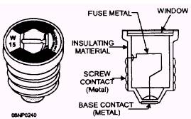
Panelboards The service entrance terminates in the service equipment or in a panelboard. The panelboard may be used for lighting and power branch circuits. A distribution panel, as the name implies, serves as a center or point in the electrical system where power is fed to the branch circuits. A distribution panel consists mainly of a metal cabinet that houses bus bars and individual circuit protective devices. The protective devices (fuses or circuit breakers) protect me circuits against excessive current flow. Panelboards must be rated at least as high as the feeder capacity required for the load. Panelboards are marked by the manufacturer with the voltage, current rating, and number of phases for which they are designed. This information, plus the manufacturer's name or trademark, is not to be obstructed by interior parts or wiring after the panelboard is installed. According to the NEC(c), lighting and appliance panelboards cannot have more than 42 overcurrent devices besides the mains. Two-pole and three-pole circuit breakers are connected as two and three overcurrent devices, respectively. According to the NEC(c), each lighting and appliance panelboard must be protected from current flow on the supply side by not more than two main circuit breakers or two sets of main fuses that have a combined rating no greater than that of the panelboard. This protects not only the feeders but also the panelboard. The panelboard does not need individual protection if the panelboard feeder has overcurrent protection no higher than the panelboard rating. The total load on any single overcurrent device in a
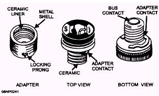
Figure 5-61.- Plug type of fuse. panelboard must not exceed 80 percent of its capacity where, in normal use, the load continues for 3 hours or longer to prevent overheating of the conductor. Panelboard cabinets must be grounded. A terminal bar must be provided for attachment of feeder and branch circuit equipment-grounding conductors where nonmetallic raceway or cable is used. This terminal bar must be bonded to the cabinet, but not to the neutral bar except in service equipment. Three-phase panelboards supplied by a four-wire, delta-connected system that has the midpoint of one phase grounded must have the higher voltage-to-ground conductor or bus bar marked. This high-voltage conductor should have an orange outer finish or be clearly tagged. The identification is required at any point where a connection can be made and the neutral conductor is also present. The phase arrangement on a three-phase panelboard is A, B, C, from left to right, or top to bottom when viewed from the front. The B phase will be the phase that has the higher voltage-to-ground. There are two basic types of panelboards: fuse panels and circuit breaker panels. Fuse panels, as the name implies, contain fuses for protection of each circuit. Fuse panels are designed in a variety of ways. These designs vary in size, capacity (amperage and voltage), and type of installed fuses. The capacity of the panel is based on the ampacity of the bus bars of the panel. The number of bus bars is determined by whether the panel is single-phase or three-phase. Fuse panels are designed for plug fuses, cartridge fuses, knife-blade fuses, or a combination of these. Fuse panels use an Edison-base fuse that screws into a socket similar to the medium-based light socket. Fuse panels still exist but are not very common. Fuse panels are not to be installed either for new work or as a replacement panel unless they have been modified to accept Type S fuses. Refer to figure 5-61 for a view of the plug type of fuse and figure 5-62 for a view of the adapter and Type S fuse.
Figure 5-62.- Adapter and Type S fuses.
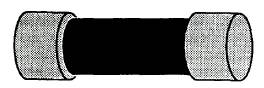
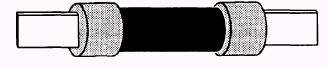
Figure 5-63.- Ferrule type of fuse. The other type of fuse you will be dealing with, as a CE, is the cartridge fuse. There are two types: the ferrule and the knife blade. Both types are available with replaceable or nonreplaceable fuse links. Ferrule fuses are available in ampere ratings from 0 through 60. Fuse panels that use the ferrule type of fuse have specially designed fuse clips in which only ferrule types will fit. Fuse diameter and length increase as amperage and voltage increase. Ferrule fuses are used in circuits up to 600 volts. Figure 5-63 shows a typical ferrule type of fuse. Fuse panels that provide distribution for high-capacity circuits use knife-blade fuses for protection. The fuse clips are especially designed to receive knife-blade fuses only. Knife-blade fuses are available in ampere ratings of 61 through 6,000. The maximum voltage rating for knife-blade fuses is 600 volts. Figure 5-64 shows a typical knife-blade fuse. Two factors must be considered when fuses for circuit protection are to be selected. These are the total current flow and the voltage of the circuit in which the fuse is to be installed. Since the purpose of the fuse is to protect the circuit, it must be the weakest point in the circuit. Thus the fuse used should be rated no higher than the lowest rated component to be protected. Before installing a fuse in a panel; check the condition of the
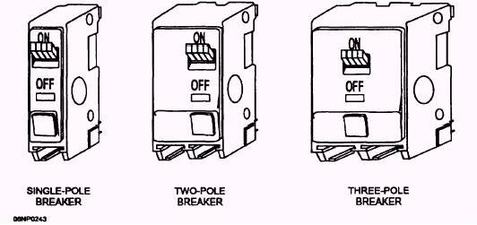
Figure 5-64.- Knife-blade fuse. fuse holder or clips. These must be clean and hold the fuse firmly. One of the newer types of protective devices, used more often than fuses because of the way it reacts to an overload, is the circuit breaker. A circuit breaker trips on an overload but can be reset to complete the circuit again without having to be removed or replaced. Circuit breakers are classed according to their operating principle. They may be thermal, magnetic, or a combination of thermal and magnetic. Figure 5-65 shows typical circuit breakers with one, two, and three poles. Multipole breakers are designed to open all ungrounded conductors in a circuit at the same time. A thermal type of circuit breaker has a bimetallic element within the breaker that responds to temperature change. The bimetallic element is made by fusing together two strips of dissimilar metal. Each strip has a different expansion rate when heated. Current flowing through the breaker generates heat, which increases as the flow increases. The heat causes the bimetallic element to bend and act against a latch. The breaker mechanism is adjusted so that when the current flow reaches a set level, the element bends enough to trip the latch. This action opens a set of contacts to break the circuit. The thermal type of circuit breaker is commonly called a time lag breaker because the breaker
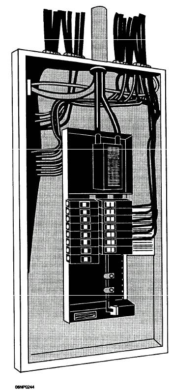
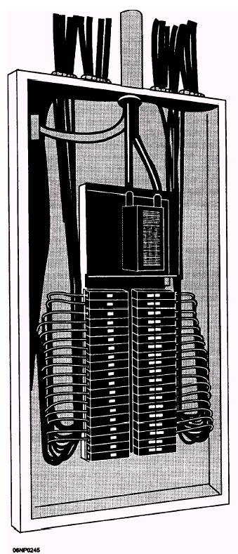
Figure 5-65.- Typical circuit breakers. does not open immediately when an overload occurs. The bimetallic element requires a short time (length depends on the size of the overload) to respond to the heat generated by the overload current. A magnetic type of circuit breaker responds instantaneously when an excess of current flows through the breaker. A small electromagnet is used to actuate the breaker mechanism. Whenever a predetermined amount of current flows through the electromagnet, enough magnetic flux is created to attract a small armature. As the armature moves, the breaker mechanism trips and opens the circuit. The thermal-magnetic circuit breaker, as the name implies, combines the features of both the thermal and the magnetic types. Of the three, the thermal-magnetic circuit breaker is preferred for general use. A small overload actuates the bimetallic strip to open the circuit on a time delay, while a large overload or short circuit actuates the magnetic trip to open the circuit instantaneously. Circuit breakers are rated in amperes and volts the same as fuses and you select them on the same basis. Circuit breakers are sealed units and no attempt should be made to repair them or to adjust the ampere capacity. A defective breaker must be removed and replaced. 5-34 Circuit breakers that are to be used in circuits that may pose an added hazard to the user are made with an extra safety feature. This breaker is called a ground fault circuit interrupter (GFCI). It is a thermal-magnetic breaker with an additional internal circuit that detects a current leak from the hot wire to ground and opens the breaker if that current reaches a set amount. This leakage cannot be more than 5 ( 1) milliamperes (thousandths of an ampere) to ground. Most of these breakers have a test button that can be used to check the GFCI to see if it will trip when there is a fault. To install the GFCI, you connect the circuit hot wire to the breaker the same as you do on a standard breaker. The circuit neutral is connected to another terminal on the GFCI instead of to the neutral bar in the panel. The GFCI comes with an attached white neutral wire, which you then connect to the neutral bar. The NEC(c) requires that GFCIs be installed for several circuits used in the home. These circuits include ALL 120-volt, single-phase, 15-and 20-ampere receptacles in bathrooms, garages, and outdoors. GFCIs may be used elsewhere when there is a need for the added protection. Now that we have discussed the various types of panelboards, fuses, and circuit breakers, we need to discuss panelboard connections. Once the circuits have all been brought into the cabinet, the panelboard can be mounted in the cabinet. Also, the neutral bar and the equipment ground bar are attached to the cabinet. The ground bar must be bonded to the cabinet by either a bonding jumper or the more common method of running a screw through the bar into the cabinet. The equipment ground bar and the neutral bar are not bonded together unless the panelboard also serves as the service equipment. Quite often the panelboard is not connected until the interior wiring is done and the receptacles, switches, and fixtures have been installed. The method of attaching circuit conductors is based on conductor size and type of terminals on the panelboard. Small conductors, No. 10 and smaller, are normally looped around a screw type of terminal. Larger conductors may need to have terminal lugs, attached so the connection can be made to screw terminals. Pressure types of terminals are often provided for larger conductors, neutral conductors, and equipment-grounding conductors. Conductors should be connected in a neat and professional manner. In many cases, conductors are connected with little excess wire. Conductors brought in through the sides of the cabinet are connected directly to the overcurrent device. Those brought in from the top or bottom of the cabinet are bent neatly opposite the fuse or circuit breaker to which they are to be attached and cut just long enough to make a good connection, as shown in figure 5-66. However, many experienced electricians feel that this system of connecting conductors is not necessarily the best, even though it presents the most uncluttered look and leaves more space around each conductor. These electricians usually try to leave an end on each conductor that is equal to the height plus the width of the cabinet. Each conductor is run along the panel and looped back 180 degrees before being connected to its fuse or circuit breaker. This method is shown in figure 5-67. Little added material is needed, and the extra length on the conductor permits it to be switched to another terminal on the panel if desired. Also, in the case of conductor breakage near the terminal, the conductor can be reconnected easily. The ungrounded conductors in a fuse panelboard are connected directly to terminals on the bus bars. In a circuit breaker panelboard, the underground conductors are usually connected to the circuit breaker. The circuit breaker is then inserted in the panelboard. In most cases, the breaker is snapped into place and is held by spring tension. Sometimes breakers are held in the panelboard by a screw.
Figure 5-66.- Panelboard connections without excess wire.
Figure 5-67.- Panelboard connections with leaped conductors.
|
 |
|
|