Custom Search
|
|
  |
|
|
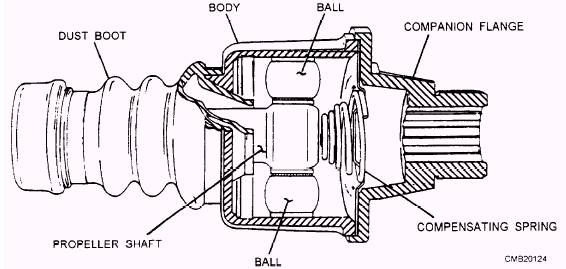
The speed fluctuations caused by the conventional universal joints do not cause much difficulty in the rear-wheel drive shaft where they have to drive through small angles only. In front-wheel drives, the wheels are cramped up to 30 degrees in steering. For this reason velocity fluctuations present a serious problem. Conventional universal joints would cause
Figure 5-6.- Ball and trunnion universal joint. hard steering, slippage, and tire wear each time the vehicle turns a corner. Constant velocity joints eliminate the pulsations because they are designed to be used exclusively to connect the front axle shaft to the driving wheels. Basic operation of a CV joint is as follows: The outboard CV joint is a fixed joint that transfers rotating power from the axle shaft to the hub assembly. The inboard CV joint is a sliding joint that functions as a slip joint in a drive shaft for rear-wheel drive vehicles. The constant velocity joints you will normally encounter are the Rzeppa, Bendix-Weiss, and tripod types. Rzeppa Constant Velocity (CV) Joint
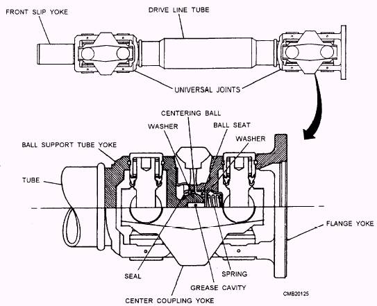
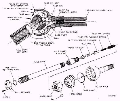
Figure 5-7.- Double-cardan universal joint. of driving contact between the two halves of the coupling. A Rzeppa CV joint consists of a star-shaped inner race, several ball bearings, bearing cage, outer race or housing, and a rubber boot (fig. 5-8). The inner race (driving member) is splined to the inner axle shaft. The outer race (driven member) is a spherical housing that is an integral part of the outer shaft; the balls and ball cage are fitted between the two races. The close spherical fit between the three main members supports the inner shaft whenever it is required to slide in the inner race, relieving the balls of any duty other than the transmission of power. The movement of the balls is controlled by the ball cage. The ball cage positions the balls in a plane at right angles to the two shafts when the shafts are in the same line. A pilot pin, located in the outer shaft, moves the pilot and the ball cage by simple leverage in such a manner that the angular movement of the cage and balls is one half of the angular movement of the driven shaft. For example, when the driven shaft is moved 20 degrees, the cage and balls move 10 degrees. As a result. the balls of the Rzeppa joint are positioned, from the top view, to bisect the angle formed.
Figure 5-8.- Rzeppa constant velocity (CV) joint. |
 |
|
|