Custom Search
|
|
  |
|
|
Time-Release Mechanism Check-out
The time-release mechanism must be re-moved from the ejection seat to perform
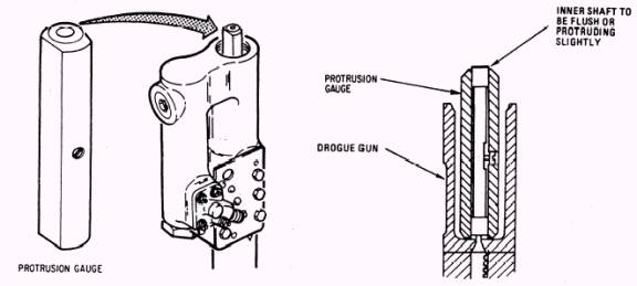
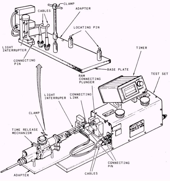
Figure 6-26.- Drogue gun firing pin protrusion check-out this check-out. You should ensure the TRM is disarmed before performing maintenance on it. Then, remove the firing body from the time-delay g-sensing release mechanism. Re-move the lockwire from the firing link and remove the hex head plug and washer from the base of the unit. Inspect the TRM for damage and/ or corrosion. If damaged or corroded, check the MIM for corrective action to be taken. Time Delay Check-Out To complete the time delay check-out, you should perform the following steps in sequence. 1. Remove the light interrupter from the test set and screw it into the base of the time-delay g-sensing release mechanism, as shown in figure 6-27. Install the TRM adapter on the time-delay test set base. Connect the adapter
Figure 6-27.- Time-release mechanism time delay check-out electrical cables to the time-delay set timer. Then connect the test set to a 110-volt ac 60-Hz power supply. Again, you will need an air source regulated to 80 psi. 2. Extend the ram connecting plunger on the test set by pressing the reset button. Position the TRM on the test set and secure it with a test set clamp. Attach the time-delay g-sensing release mechanism firing link to the test set ram connecting plunger, connecting link, and con-necting pins. NOTE: At this point, you should ensure QA personnel are present to witness the elapsed time function. 3. Press the time-delay test set actuate button and record the time required to pull the firing link from the time-release g-sensing release mechanism. The elapsed time should not exceed 1.5 0.1 seconds. If the time is greater than 1.5 0.1 seconds, the unit must be replaced.
|
 |
|
|