Custom Search
|
|
  |
|
|
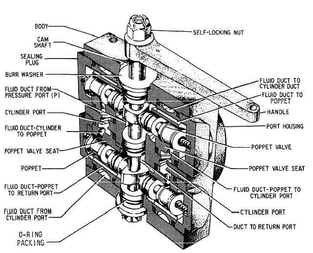
Poppet-Type Selector Valve Poppet-type selector valves are manufactured in both the balanced and unbalanced design. An unbalanced poppet selector valve offers unequal working areas on the poppets. The larger area of the poppet is in contact with the working lines of the system; consequently, when excessive pressure exists within the working lines due to thermal expansion, the poppet will open. This action allows the excessive pressurized fluid to flow into the pressure line, where it is relieved by the main system relief valve.The balanced poppet selector valve has equal poppet areas. The poppets will remain in the selected position during thermal expansion of working line fluid. For this reason, thermal relief valves are installed in working lines that incorporate balanced poppet selector valves.Figure 8-7 shows a typical four-port poppet selector valve. This is a manually operated valve, and consists of a group of conventional spring-loaded poppets. The poppets are enclosed in a common housing and interconnected by passageways to direct the flow of fluid in the desired direction.
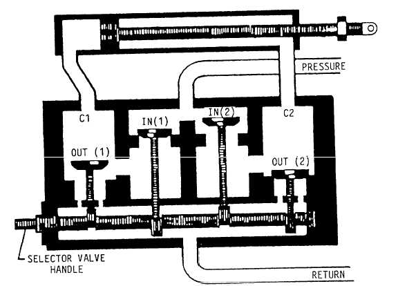
All poppet-type selector valves are provided with a stop for the camshaft. The stop is an integral part of the shaft, and strikes against a stop pin in the body to prevent overrunning. A poppet selector valve housing usually contains poppets, poppet seats, poppet springs, and a camshaft. When the camshaft is rotated, either clockwise or counterclockwise from neutral, the cam lobes unseat the desired poppets and allow a fluid flow. One cam lobe operates the two pressure poppets, and the other lobe operates the two return poppets. To stop the rotation of the camshaft at an exact position, a stop pin is secured to the body, and extends through a cutout section of the camshaft flange. This stop pin prevents overtravel by ensuring that the cam lobes stop rotating when the poppets have been unseated as high as they can go, where any further rotation would allow them to return to their seats. The poppet-type selector valve has three positions-neutral and two working positions. In the neutral position, the camshaft lobes are not contacting any of the poppets. This position assures that the poppet springs will hold all four poppets firmly seated. With all poppets seated, there is no fluid flow through the valve. This action also blocks the two cylinder ports, so when this valve is in neutral, the fluid in the unit system is trapped. To allow for thermal expansion buildup, thermal relief valves must be installed in both working lines.
Return fluid coming from the actuator is coming in the other cylinder port, through the diagonal fluid passages, past the unseated return poppet, through the vertical fluid passages, and out the return port to the system reservoir. By rotating the camshaft in the opposite direction until the stop pin hits, the opposite pressure and return poppets are unseated, and the fluid flow is reversed. This causes the actuator to move in the opposite direction. Selector valves should be checked periodically for leakage and security of mounting. The operating linkage should be inspected for ease of operation. Malfunctioning selector valves are usually the result of foreign particles or damaged parts. A malfunctioning valve should be removed and checked for free movement of the camshaft. The valve maybe disassembled and all parts cleaned with clean hydraulic fluid. O-rings should be replaced while the valve is disassembled. Both external and internal leakage may be caused by damaged or worn O-rings. External leakage could be caused by a damaged gasket under the sealing plug or the end packing on the camshaft. Internal leakage could be caused by a damaged center packing on the camshaft, a damaged bottom gasket on the poppet seat, or a damaged O-ring packing on the poppet. NOTE: All selector valves that require repair or adjustment must be done in accordance with the applicable MIM or 03 manual. After repair or adjustment, all valves must be tested for proper operation and leakage.
|
 |
|
|