Custom Search
|
|
  |
|
|
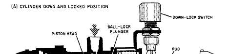
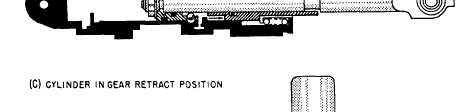
Mechanical-Lock Actuating Cylinder In many installations it is necessary to lock an actuating cylinder in a specified position. This may be for safety or operational requirements of the unit. The different designs of lock cylinders vary between manufacturers, but they are usually of the ball-lock or finger-lock type. At times, indicating devices are also incorporated along with the lock feature of the cylinders.BALL-LOCK ACTUATOR. The cylinder shown in figure 8-3 is a single-action, ball-lock
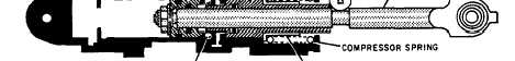
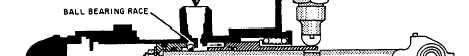
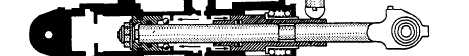
The main parts of this cylinder are the body, end caps, piston shaft and head, ball-lock plunger, locking ball bearings, ball bearing race, spring guide, compression spring, and down-lock switch. The operation of the ball-lock actuator is described in the following paragraphs. When the landing gear is down and locked, the ball-lock actuator will be in the position shown in view A of figure 8-3. Notice the locking ball bearings are being held in the ball bearing race detents by the inner lip of the ball-lock plunger. Since no hydraulic pressure exists while in this position, the spring-loaded, ball-lock plunger is held in its retracted position, allowing the down-lock switch to be actuated by the groove portion of the piston shaft. When the landing gear selector valve is positioned to its retracted (UP) position, pressurized fluid is allowed to enter the actuator through its only port. This pressurized fluid forces the ball-lock plunger to the right, which simultaneously allows the ball bearings to drop free from their detents in the bearing race and actuate the down-lock switch, as shown in view B of figure 8-3. As soon as the locking ball bearings are released, the piston shaft assembly retracts, as shown in view C of figure 8-3, and unlocks the landing gear. When the landing gear completes its UP cycle, the selector valve returns to neutral, trapping hydraulic fluid within the actuator until the next cycle begins. FINGER-LOCK ACTUATOR. The actuating cylinder shown in figure 8-4 is a double-action, two-port, finger-lock, balanced actuator. This type of actuator is currently installed as a main landing gear component on some aircraft. It incorporates an inner cylinder to equalize the displacement of fluid on either side of the piston.As shown in view A of figure 8-4, an integral, finger-type, spring-loaded, mechanical lock is also incorporated within the actuator to lock the piston shaft assembly in the extended position. The finger-lock actuator has a down-limit switch mounted on and through the cylinder area, which indicates when the landing gear is down and locked; also, an added feature that is common on landing gear actuators is an integral shuttle valve. The shuttle valve allows connection of both the normal extension hydraulic fluid line and the emergency pneumatic extension pressure line. The operation of the finger-lock actuator is described in the following paragraphs.When the pilot positions the selector valve in the landing gear retracted position, view A of figure 8-4, hydraulic pressure is directed to the cylinders retract port. Hydraulic pressure entering the cylinder overcomes piston spring force, which permits the locking fingers to open as the piston shaft assembly is retracted into the cylinder.During normal extension of the landing gear (view B of figure 8-4), hydraulic pressure is directed from the selector valve to the normal extension port of the integral shuttle valve. This pressurized fluid forces the piston towards the extended position. As the piston comes in contact with the locking fingers, hydraulic pressure and spring tension are required to force the piston over the fingers while fully extending the piston shaft assembly. At the same time the piston is being forced over the locking fingers, it contacts the cam-shaped lower end of a toggle shaft, which extends radially into the cylinder area, thereby rotating the shaft. Movement of the toggle shaft is transmitted to the main landing gear down-limit switch, which is attached to the outer surface of the cylinder. This indicates the cylinder is in the locked position. |
 |
|
|