Custom Search
|
|
  |
|
|
Solenoid-Operated Selector Valve A solenoid-operated selector valve is an electrically controlled valve. Solenoid-operated selector valves may be either the slide type or the poppet type. They differ from the manually controlled valves previously described in that they are electrically controlled by one or more solenoids contained within the valve.A solenoid may be defined as a hollow or tubular-shaped electric coil, made up of many turns of fine insulated wire, that possesses the same properties as an electromagnet. The hollow core imparts linear motion to a movable iron core (or plunger) placed within the hollow core of the solenoid.
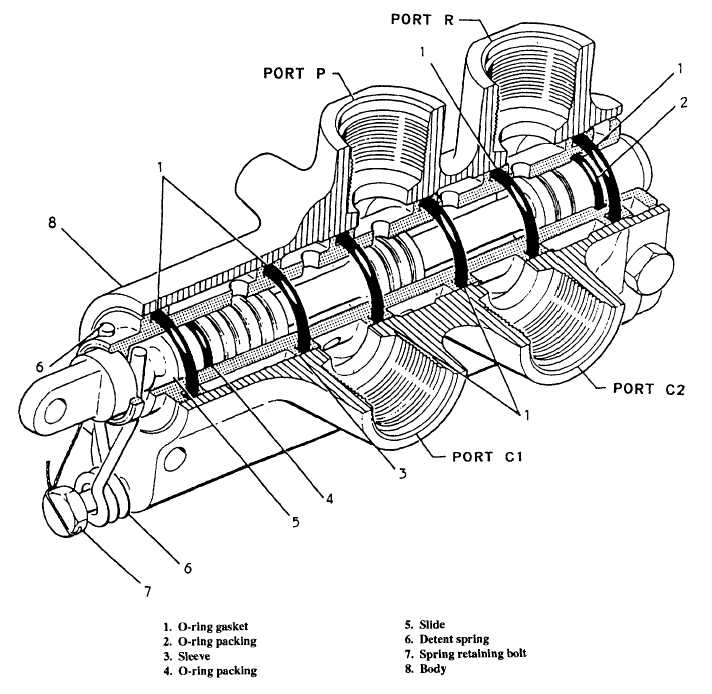
The body is bored through lengthwise to receive a slide and sleeve assembly similar to the slide-type valve previously described. All four fluid ports lead into this body bore. The ends are closed off by caps or plugs. A hollow steel sleeve is pressed into the body bore. There are no flanges or grooves machined on the sleeve, but a pattern of holes has been drilled all around it. These holes are arranged in five rings, along the length of the sleeve, drilled through to the hollow center. When the sleeve is installed in the body, each ring of holes will line up with a fluid port. The return port connects to the two outboard rings of holes. To separate each ring of holes around the outside of the sleeve, six O-ring gaskets are installed in the body bore at intervals along its length. The sleeve is then inserted through the centers of the O-rings. A steel slide is fitted inside the hollow sleeve. The slide has three lands, which form a lapped fit to the inside of the sleeve. Fluid will not flow past them. By properly positioning the slide inside the sleeve, the slide lands will connect different fluid ports by opening or closing the rings of holes in the sleeve. The flow of fluid to and from the actuator is directed by the slide. When the valve is in neutral, the slide is held in the exact center of the sleeve by two coil springs. These springs, working through spring guides, apply equal pressure to each end of the slide. Variation in slide design will determine the valve porting. To position the slide, apply hydraulic pressure to the working surfaces at each end of it. This pressure is obtained from the pressure port, and is called "bleed pressure." Body passageways direct this pressure to the ends of the slide. Two solenoid assemblies are used to control the flow of bleed pressure. A solenoid is installed in each side of the valve, pointing toward the center of the body. The solenoids are tubular in shape, with coil wires wound around a hollow center. Hydraulic fluid can enter the center portion, but cannot reach the coil wires. The solenoids are held in place by threaded caps that screw into the body. The function of these solenoids is to control bleed pressure. A metal core, called a plunger, is placed in the hollow center of the solenoids. This plunger reacts to the magnetic field created when the solenoid coil is energized. The plunger sits above the level of the coil wires, so that when the solenoid is energized, the plunger is pulled down into the magnetic field. When the plunger is pulled down by the magnetic field, it drives the plunger pin ahead of it. When this happens, the pin opens a passage and relieves bleed pressure from one end of the slide. During all periodic inspections, selector valves are inspected for security of installation and external leakage. If a malfunction occurs, it must be determined whether the cause is electrical, hydraulic, or material failure. If the aircrafts hydraulic pressure and electrical current are both normal, remove the selector valve and send it to the supporting AIMD. Use the proper 03 series maintenance publication as a guide to clean, inspect, repair, and test the selector valve. Testing procedures are thoroughly outlined in the MIMs and 03 series manuals. In general, these procedures will consist of checking for internal and external leakage, and on electrically controlled valves, testing the operation of the solenoids. Before applying pressure, make sure all air is bled out of the valve; otherwise, a leak may exist but go undetected. As the testing procedure begins and after the air has been bled, the selector valve shouId be subjected to a low pressure for a short period of time to allow all parts to be lubricated and all O-rings to seat. If the valve is to be stored prior to use, it must be filled with preservative hydraulic fluid, then drip drained before capping. |
 |
|
|