Custom Search
|
|
  |
|
|
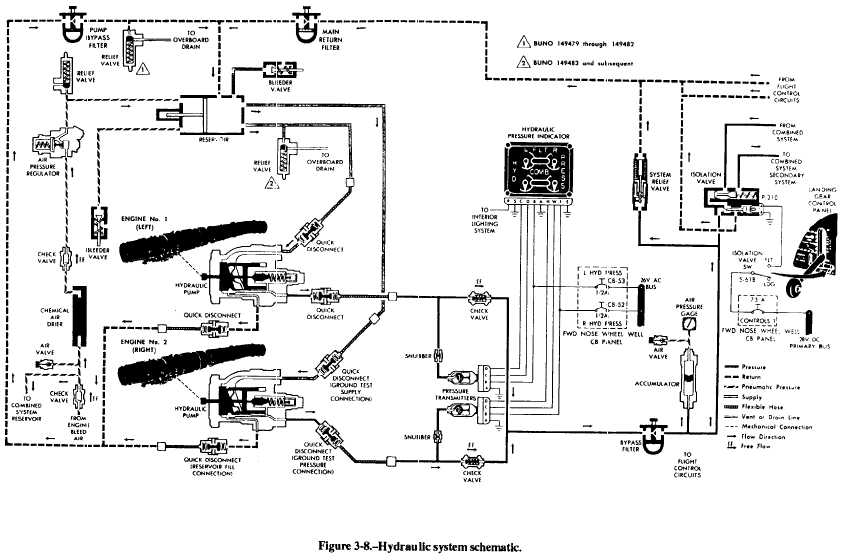
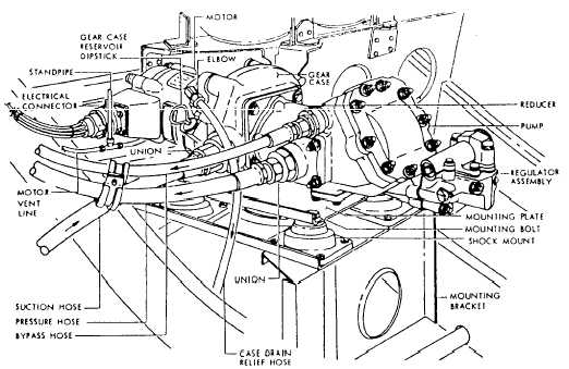
DIAGRAMS One of the more important factors in trouble-shooting a system logically is your understanding of the components and how they operate. You should study the information and associated schematics provided in the MIM. The function of each component and possible malfunctions can be used in the process of analyzing actual malfunction symptoms.A primary concern in troubleshooting an aircraft hydraulic system is to determine whether the mal-function is caused by hydraulic, electrical, or mechan-ical failure. Actuating systems are dependent on the power systems. Some of the troubles exhibited by an actuating system may be caused by difficulties in the power system. A symptom indicated by a component of the power system may be caused by leakage or malfunction of one of the actuating systems. When any part of the hydraulic system becomes inoperative, use the diagrams in conjunction with the checkout procedures provided in the aircraft MIM. Possible causes of trouble should always be eliminated systematically until the pertinent cause is found. No component should be removed or adjusted unless there is a sound reason to believe the unit is faulty.
|
 |
|
|