Custom Search
|
|
  |
|
|
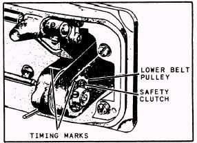
SINGER SEWING MACHINE 211 W 151 This machine performs the same functions as the 111 W 151. It is a newer model, more streamlined and modern in appearance, and has some design features not found in the 111 W 151 machine. (See figure 9-3 1.) These features include a new lubrication system, a thread take-up lever guard, a thread lubricator, and a new stitch indicator. The 211 W 151 sewing machine is a high-speed (4,000 rpm maximum), single-needle, lockstitchtype machine, designated for sewing medium to heavyweight fabrics. It is belt-driven and has a rotary hook on a vertical axis, which makes two revolutions for each stitch. It has a safety clutch (fig. 9-32) that is adjustable to suit the sewing conditions; this protects the sewing hook from damage. If the hook is obstructed by foreign matter, the clutch will disengage and re-engage only after the area has been cleared. The feeding mechanism is a compound drop and needle feed with the longest stitch at five stitches per inch.
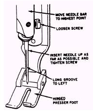
Figure 9-32.-Safety clutch and lower belt pulley. Other features of the machine include a hinged presser foot, a presser bar lift of 1/4 inch, a needle bar stroke of 1 5/16 inches, a bed that is 20 3/8 inches long by 7 inches wide, and a space of 10 1/2 inches to the right of the needle. Needles The needles used in this machine vary according to the clearance under the presser foot. Use 135 x 7 needles with machines set with 1/4-inch clearance under the presser foot, and 135 x 17 needles with those set with 3/8-inch clearance (lift). Adjustments Adjustments to the 211 W 151 are basically the same as for 111 W 151. These adjustments are discussed in the following text. SETTING THE NEEDLE BAR.- Place the needle bar up into the needle bar holder as far as possible. Hold in this position and turn the balance wheel toward the operator until the needle bar is at its lowest position. When in this position, set the bar so the upper timing mark is just visible below the needle bar frame, and tighten the needle bar connecting stud pinch screw. In case the needle bar does not have timing marks, set the machine to zero stitches per inch and place the needle bar up in the holder as far as possible. Turn the balance wheel by hand until the bar is at its lowest position. After reaching the lowest position of the needle bar, continue turning the balance wheel toward the operator until it reaches 3/32 inch above its lowest point, then set the eye of the needle 1/16 inch below the point of the sewing hook. SETTING THE NEEDLE.- To set the needle, insert the needle shank as far as possible into the needle bar with the long groove of the needle to the left and tighten the screw. (See figure 9-33.)
Figure 9-33.-Setting the needle.
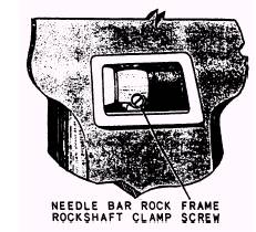
Figure 9-34.-Needle bar rock frame rockshaft damp screw. RELATIVE POSITION OF' NEEDLE BAR AND PRESSER BAR.- To set the relative position of the needle bar to the presser bar, loosen the needle bar rock frame rockshaft clamp screw, which is located behind the cover plate on the front upright position of the arm (fig. 9-34). Set the needle bar so the distance between the needle bar and presser bar is 17/32 inch. Retighten the clamp screw. NOTE: A handy tool for this adjustment can be manufactured locally from a thin piece of metal stock filed to exactly 17/32-inch width. This gauge should be placed between the two bars while the clamp screw is being tightened. This enables the operator to keep pressure on the loose needle bar. ADJUSTMENT HEIGHT OF SEWING HOOK.- Before attempting to adjust the height of the sewing hook, it is necessary to make a feeler gauge for testing the height. This gauge can be made of 0.032-inch shim stock, or a regular feeler gauge can be cut or trimmed down so it will fit in the small groove in the throat plate, which retains the bobbin case stop finger. If, after testing, the hook height is unsatisfactory, turn the balance wheel so the two setscrews in the bottom of the hook are accessible; loosen them with an Allen wrench. Remove the cloth washer from the bobbin case and turn the hook until the height adjusting screw is directly
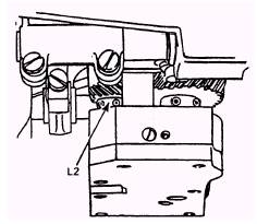
Figure 9-35.-Timing tbe sewing hook. under the hole in the bobbin case. (See figure 9-35.) Turn the screw into raise the hook, and out (while pressing down on the hook) to lower it. The gauge should barely pass between the throat plate and bobbin case stop finger. Retighten the Allen setscrews and turn the adjusting screw in so that a slight tension is left on the screw. SETTING SEWING HOOK TO OR FROM NEEDLE.- To set the relative position of the hook saddle to the needle, loosen the hook saddle adjusting screws (fig. 9-36) and slide the hook saddle to the right or left, as necessary, to set the point of the hook as close to the needle as possible (without actually touching). After setting the hook saddle, check the clearance between the hook drive gear and the face of the hook saddle. This clearance should be 0.008 inch; if it is not, reset it by loosening the screw and setscrew in the hook drive gear, and move the gear to the right or left to get the proper clearance. |
 |