 |
||
|
|
||
|
Page Title:
PLACING AND TYING REINFORCING STEEL |
||
| |||||||||||||||
|
|
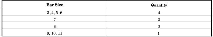
PLACING AND TYING REINFORCING STEEL Before you place reinforcing steel in forms, all form oiling should be completed. Oil on reinforcing bars should be avoided because it reduces the bond between the bars and the concrete. Use a piece of burlap to remove rust, mill scale, grease, mud, or other foreign matter from the bars. A light film of rust or mill scale is not objectionable. Bars are marked to show where they will fit. You may work according to either one of the two most-used systems for marking bars; however, the system you use should agree with the marking system which appears on the engineering or assembly drawings. The two marking systems used are as follows: 1. All bars in one type of member are given the mark of that member. This system is used for column bars, beam bars, footing bars, and so on. 2. The bars are marked in greater detail. These marks show exactly where the bar is to be placed. In addition to the type member (that is, beam (B), wall (W), column (C), and so on), the marks show the floor on which the bars are to be placed and the size and individual number of each particular bar. Instead of showing the bar size by its diameter measurement, the mark shows the bar size in code by eighths. The examples shown below show the second type of marking system. 213805 2 = second floor B = beam member 8 = 8/8- or 1 -inch (2.5 cm)-square bar 05 = part of the second floor plan designated by the number 5 2130605 2 = second floor B = beam member 06 = 6/8- or 3/4-inch (1.9 cm)-round bar 05 = part of second floor plan designated by the number 5 Tie wire is used to hold rebar in place to ensure that when concrete is placed the bars do not shift out of position. Sixteen gauge wire is used to tie Table 7-6.-Multishearing
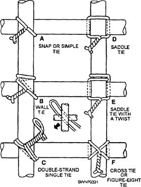
reinforcing bars. About 12 pounds (5.4 kg) of wire is required to tie an average ton (0.9 tome) of bars. NOTE: Tie wire adds nothing to the strength of the steel. A number of different types of ties can be used with reinforcing bars; some are more effective than others. Figure 7-17 shows six types of ties that are identified below according to the letters of the alphabet used to show individual ties. A. SNAP TIE or SIMPLE TIE. The wire is simply wrapped once around the two crossing bars in a diagonal manner with the two ends on top. These are twisted together with a pair of sidecutters until they are very tight against the bars. Then the loose ends of the wire are cut off. This tie is used mostly on floor slabs. B. WALL TIE. This tie is made by going about 1 1/2 times around the vertical bar, then diagonally around the intersection, twisting the two ends together until the connection is tight, but without breaking the tie wire, then cutting off the excess. The wall tie is used on light vertical mats of steel. C. DOUBLE-STRAND SINGLE TIE. This tie is a variation of the simple tie. It is especially favored for heavy work D. SADDLE TIE. The wires pass halfway around one of the ban on either side of the crossing bar and are brought squarely or diagonally around the crossing bar with the ends twisted together and cut off. This tie is used on special locations, such as on walls. E. SADDLE TIE WITH TWIST. This tie is a variation of the saddle tie. The tie wire is carried completely around one of the bars, then squarely across and halfway around the other, either side of the crossing bars, and finally brought together and twisted either squarely or diagonally across. The saddle tie with twist is used for heavy mats that are to be lifted by a crane. F. CROSS TIE or FIGURE-EIGHT TIE. This type of tie has the advantage of causing little or no twist in the bars. The proper location for the reinforcing bars is usually given on drawings (table 7-7). In order for the structure to withstand the loads it must carry, place the steel in the position shown. Secure the bars in position in such a way that concrete-placing operations will not move them. This can be accomplished by the use of the reinforcing bar supports shown in figures 7-18, 7-19, and 7-20.
Figure 7-17.-Six types of ties.
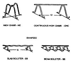
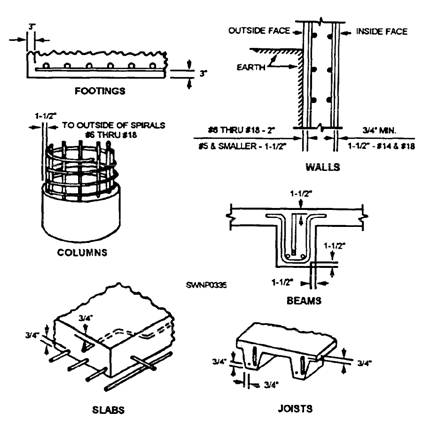
Figure 7-18.-Reinforcement bar accessories. The proper coverage of bars in the concrete is very important to protect the bars from fire hazards, possibility of corrosion, and exposure to weather. When not specified, minimum standards given below and in figure 7-21 should be observed. FOOTINGS-3 inches at the sides where concrete is cast against the earth and on the bottoms of footings or other principal structural members where concrete is deposited on the ground.
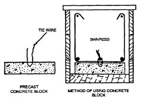
Figure 7-19.-Precast concrete block used for rebar support. WALLS-2 inches for bars larger than No. 5, where concrete surfaces, after removal of forms, would be exposed to the weather or be in contact with the ground; 1 1/2 inches for No. 5 bars and smaller; 3/4 inch from the faces of all walls not exposed directly to the ground or the weather. COLUMNS-1 1/2 inches over spirals and ties. BEAMS AND GIRDERS-1 1/2 inches to the nearest bars on the top, bottom, and sides. JOISTS AND SLABS-3/4 inch on the top, bottom, and sides of joists and on the top and the bottom of slabs where concrete surfaces are not exposed directly to the ground or the weather. NOTE: All measurements are from the outside of the bar to the face of the concrete, NOT from the main steel, unless otherwise specified. Footings and other principal structural members that are against the ground should have at least 3
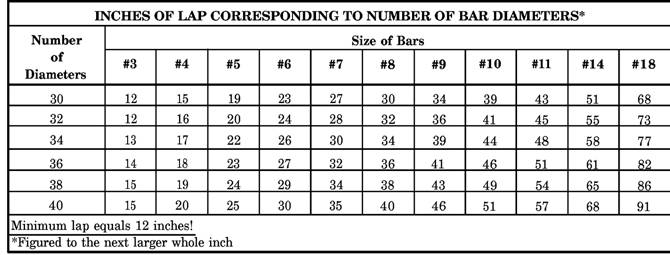
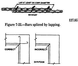
Figure 7-20.-Rebar hung in place. inches (76.2 mm) of concrete between the steel and the ground. If the concrete surface is to be in contact with the ground or exposed to the weather after removal of the forms, the protective covering of concrete over the steel should be 2 inches (50.8 mm). It maybe reduced to 1 1/2inches (38.1 mm) for beams and columns and 3/4 inch (19.5 mm) for slabs and interior wall surfaces, but it should be 2 inches (50.8 mm) for all exterior wall surfaces. This measurement is taken from the main rebar, not the stirrups or the ties. NOTE: Where splices in reinforcing steel are not dimensioned on the drawings, the bars should be lapped not less than 30 times the bar diameter nor less than 12 inches (table 7-7). The stress in a tension bar Table 7-7.-Length of Lap Splices in Reinforcing Steel
Figure 7-21.-Minimum coverage of rebar in concrete. can be transmitted through the concrete and into another adjoining bar by a lap splice of proper length. To lap-weld wire fabric/wire mesh, you can use a number of methods, two of which are the end lap and the side lap. In the end lap method, the wire mesh is lapped by overlapping one full mesh, measured from the ends of the longitudinal wires in one piece to the ends of the longitudinal wires in the adjacent piece, and then tying the two pieces at 1-foot 6-inch (45.0 cm) centers with a snap tie. In the side lap method, the two longitudinal side wires are placed one alongside and overlapping the other and then are tied with a snap tie every 3 feet (.9 m). Reinforcing bars are in tension and therefore should never be bent around an inside corner beams. They can pull straight through the concrete cover. Instead, they should overlap and extend to the far face for anchorage with 180-degree hooks and proper concrete coverage (fig. 7-23). The bars can also be spliced by metal are welding but only if called for in the plans and specifications. For bars which are placed in a vertical position, a butt weld is preferred. The end of the bottom bar is cut
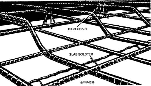
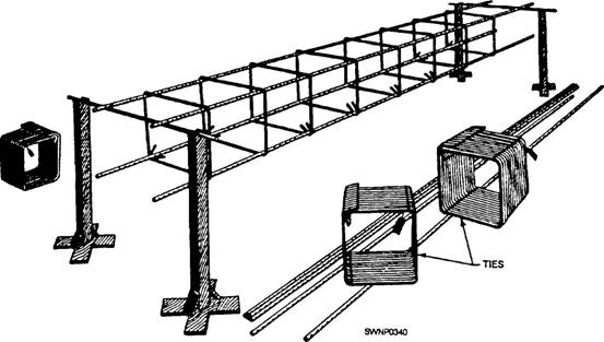
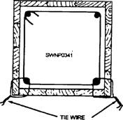
Figure 7-23.-Correct and Incorrect placement of reinforcement for an inside corner. square, and the end of the top bar resting on it is cut in a bevel fashion, thus permitting a butt weld. For bars which will bear a load in a horizontal position, a fillet weld is preferred. Usually, the two bars are placed end to end (rather than overlapping), and pieces of flat bar (or angle iron) are placed on either side. Fillet welds are then made where the metals join. The welds are made to a depth of one half of the bar diameter and for a length eight times the bar diameter. The minimum clear distance between parallel bars in beams, footings, walls, and floor slabs should either be 1 inch (25.4 mm) or 1 1/3 times the largest size aggregate particle in the concrete, whichever distance is greater. In columns, the clear distance between parallel bars should be not less than 1 1/2 times the bar diameter or 1 1/2 times the maximum size of the coarse aggregate. Always use the larger of the two. The support for reinforcing steel in floor slabs is shown in figure 7-24. The height of the slab bolster is determined by the required concrete protective cover. Concrete blocks made of sand-cement mortar can be used in place of the slab bolster. Wood blocks should never be used for this purpose. Highchairs (fig. 7-18) can be obtained in heights up to 6 inches (15 cm). When a height greater than 6 inches is required, make the chair out of No. 0, soft, annealed iron wire. To hold the bars firmly in position, you should tie the bars together at frequent intervals where they cross with a snapat. Steel for column ties may be assembled with the verticals into cages by laying the vertical bars for one side of the column horizontally across a couple of sawhorses. The proper number of ties are slipped over the bars, the remaining vertical bars are added, and then the ties are spaced out as required by the placing plans. All intersections are wired together to make the assembly rigid so that it may be hoisted and set as a unit. Figure 7-25 shows atypical column tie assembly. After the column is raised, it is tied to the dowels or reinforcing steel carried up from below. This holds it firmly in position at the base. The column form is erected and the reinforcing steel is tied to the column form at 5-foot (4.5-m) intervals, as shown in figure 7-26. The use of metal supports to hold beam reinforcing steel in position is shown in figure 7-8. Note the position of the beam bolster. The stirrups are tied to the main reinforcing steel with a snap tie. Wherever possible you should assemble the stirrups and main reinforcing steel outside the form and then place the assembled unit in position. Precast concrete blocks, as shown in figure 7-27, maybe substituted for metal supports. The horizontal and vertical bars are wired securely to each other at sufficiently frequent intervals to make a rigid mat. Tying is required at every second or third intersection, depending upon the size and spacing of bars, but with not less than three ties to any one bar, and, in any case, not more than 4 to 6 feet apart in either direction.
Figure 7-24.-Steel in place in a floor slab.
Figure 7-25.-Column assembly.
Figure 7-26.-Method of holding column steel in plain in formwork.
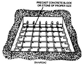
Figure 7-27.-Steel in place in a footing.
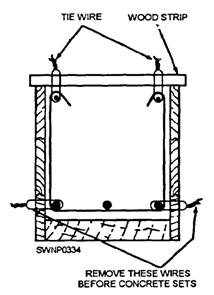
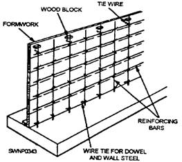
Figure 7-28.-Steel in place on a wall form Steel in place in a wall is shown in figure 7-28. The wood block is removed when the form has been filled up to the level of the block For high walls, ties in between the top and bottom should be used. Steel is placed in footings very much as it is placed in floor slabs. Stones, rather than steel supports, may be used to support the steel at the proper distance above the subgrade. Steel mats in small footings are generally preassembled and placed after the forms have been set. A typical arrangement is shown in figure 7-27. Steel mats in large footings are constructed in place. |
|
Privacy Statement - Press Release - Copyright Information. - Contact Us - Support Integrated Publishing |