 |
||
|
|
||
| |||||||||||||||
|
|
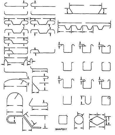
BENDING REINFORCING BARS The job of bending reinforcing bars is interesting if you understand why bending is necessary. There are several masons. Let us go back to the reason for using reinforcing steel in concrete-the tensile strength and compressive strength of concrete. You might compare the hidden action within a beam from live and dead loads to the breaking of a piece of wood with your knee. You have seen how the splinters next to your knee push toward the middle of the piece of wood when you apply force, while the splinters from the middle to the opposite side pull away from the middle. This is similar to what happens inside the beam. For instance, take a simple beam (a beam resting freely on two supports near its ends). The dead load (weight of the beam) causes the beam to bend or sag. Now, from the center of the beam to the bottom, the forces tend to stretch or lengthen the bottom portion of the beam. This pad is said to be in tension, and that is where the steel reinforcing bars are needed. As a result of the combination of the concrete and steel, the tensile strength in the beam resists the force of the load and keeps the beam from breaking apart. At the exact center of the beam, between the compressive stress and the tensile stress, there is no stress at all-it is neutral. In the case of a continuous beam, it is a little different. The top of the beam maybe in compression along part of its length and in tension along another part. This is because a continuous beam rests on more than two supports. Thus the bending of the beam is not all in one direction. It is reversed as it goes over intermediate supports. To help the concrete resist these stresses, engineers design the bends of reinforcing steel so that the steel will set into the concrete just where the tensile stresses take place. That is the reason you may have to bend some reinforcing rods in almost a zigzag pattern. The joining of each bar with the next, the anchoring of the bar ends within concrete, and the anchoring by overlapping two bar ends together are some of the important ways to increase and keep bond strength. Some of the bends you will be required to make in reinforcing bars are shown in figure 7-5. The drawings for a job provide all the information necessary for cutting and bending reinforcing bars. Reinforcing steel can be cut to size with shears or with an oxygas cutting torch. The cutting torch can be used in the field. Before bending the reinforcing bars, you should check and sort them at the jobsite. Only after you check the bars can you be sure that you have all you need for the job. Follow the construction drawings when you sort the bars so that they will be in the proper order to be bent and placed in the concrete forms. After you have divided the different sizes into piles, label each pile so that you and your crew can find them easily. For the job of bending, a number of types of benders can be used. Stirrups and column ties are normally less than No. 4 bar, and you can bend them
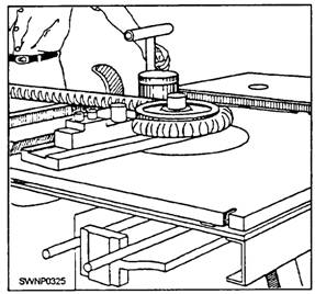
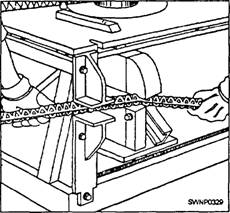
Figure 7-5.-Typical reinforcement bends.
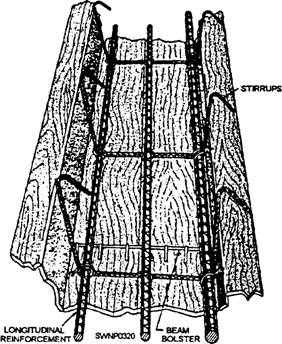
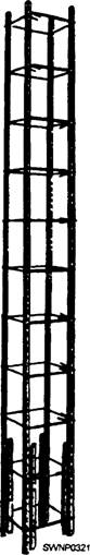
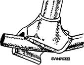
Figure 7-6.-Bar-bending table. cold by means of the bending table, as shown in figure 7-6. Typical stirrup tie shapes are shown in figure 7-7. Stirrups are used in beams; as shown in figure 7-8. Column ties are shown in position in figure 7-9. When the bars have to be bent in place, a bending tool, like the one shown in figure 7-10, is effective. By placing the jaws of the hickey on one side of the center of the bend and pulling on the handle, you can produce a smooth, circular bend through almost any angle that is desired. Bending Guidelines and Techniques Make bends, except those for hooks, around pins with a diameter of not less than six times the bar diameter for No. 3 through No. 8 bar. If the bar is larger
Figure 7-7.-Stirrup and column ties.
Figure 7-8.-Steel in place in a beam than 1 inch (25.4 mm) (No. 9, No. 10, and No. 11 bar), the minimum pin diameter should be eight times the bar size. For No. 14 through No. 18, the pin diameter should be ten times the diameter of the bar. To get smooth, sharp bends when bending large rods, slip a pipe cheater over the rod. This piece of pipe gives you a better hold on the rod itself and makes the whole operation smoother. You can heat No. 9 bars and larger to a cherry red before bending them, but make sure you do not get them any hotter. If the steel becomes too hot, it will lose strength, become brittle, and can even crack.
Figure 7-9.-Column steel in place.
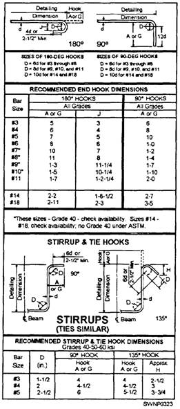
Figure 7-10.-Bending tool. Bend Diameters If you do not want your rod to crack while it is being bent, bend it gradually, not with a jerk. Also, do not make your bends too sharp. Bends made on a bar-bending table or block are usually too sharp, and the bar is somewhat weakened. Therefore, certain minimum bend diameters have been established for the different bar sizes and for the various types of hooks. These bending details are shown in figure 7-11. You can use many different types of bends. The one you select depends on where you are to place the rods. For example, there are bends on heavy beam and girder bars, bends for reinforcement of vertical columns at or near floor levels, bends for stirrups and column ties, bends for slab reinforcement, and bends for bars or wire for column spiral reinforcement. To save yourself some time and extra work, try to make all bends of one kind at one time instead of remeasuring and resetting the templates on your bending block for different bends.
Figure 7-11.-Standard hook details The Iron master Portable Hydraulic Rod Bender and Shear The Ironmaster portable hydraulic rod bender and shear (fig. 7-12) can cold-work reinforcing bars into various shapes for use in concrete construction work. The machine is capable of working reinforcing bars up to and including No. 11 bars, which is equivalent in a cross-sectional area to 1 1/4-inch (31.75 mm)square or 1 1/2-inch (38.1 mm)-round bar. In addition to all sizes of reinforcing bars, the Ironmaster will also work bars of higher carbon content desired in the fabrication of anchor bolts, and so forth. However, limitations must be imposed when considering bar of 1-inch (25.4 mm) diameter or greater that have a carbon content of greater than 0.18 percent, such as SAE 1020 cold-finished steel. Bars under 1 inch (25.4 mm) in diameter should have a carbon content of no greater than 0.37 percent, such as SAE 1040 C. F. steel. Although the Ironmaster is powered to work steels of heavier sections than 1 1/2-inch (38.1 mm) reinforcing bar, the manufacturer must place safety limitations on it when considering various alloys and shapes of steel. Users will undoubtedly adapt this versatile machine to perform work other than common bar bending, such as bending flats and angles. However, the primary intention of the manufacturer was to produce a machine for bending concrete reinforcing steel. The manufacturer recommends that the Ironmaster not be used on steels heavier than 1 1/4-inch (31.75 mm)-square or 1 1/2-inch (38.1 mm)-round reinforcing bar.
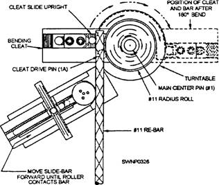
Figure 7-12.-Ironmaster portable hydraulic bender and shear. Standard Hook Bending Standard hook bending (fig. 7-13) is accomplished on the turntable section located on top of the machine. Before you start any bending procedure, the turntable must be at the START position as shown in figure 7-14. As an example, when you desire to bend a 180-degree hook in apiece of No. 11 reinforcing bar, setup the machine as shown, using the following: bending cleat with cleat slide and drive pin, main center pin, and No. 11 radius roll. As a safeguard, the radius rolls have been designed to
Figure 7-13.-Ironmaster bar-bending unit. accept only the number of bars specified, suti as No. 7 roll for No. 7 bar (fig. 7-15). 1. Plain the rebar between the cleat slide upright and the radius roll, which is placed over the center pin,
Figure 7-15.-Radius rolls for bending rebar on an Ironmaster.
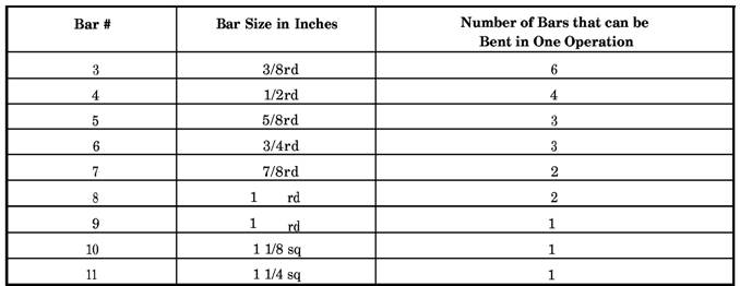
Figure 7-14.-ExampIe of bending a 180-degree hook with No. 11 rebar. with the end of the rebar protruding a sufficient distance for the cleat slide to be upright to engage it where you want the bend to commence. 2. Move the cleat slide to contact the rebar and tighten the locking screws. 3. Move the positioner slide bar until the roller contacts the rebar and tightens the T handle. 4. Set the desired angle `of bend on the graduated control rod which is under the right side of the working table. This is done by placing the trigger pin of the rear adjustable stop (toward the rear of the machine) in the hole corresponding to the angle of bend, in this case, 180 degrees. This rod is graduated from 5 degrees to 190 degrees at 5-degree intervals. NOTE: ENSURE THE FRONT ADJUSTABLE STOP TRIGGER PIN IS IN THE "O' HOLE, so the turntable will return to and stop in the START position when retracted after the bend. 5. Advance the engine throttle to operating speed, and move either the rear bending control lever or slide bending control lever to the bend position. This actuates the bend cylinder. The lever will stay in the bending position until the bend is completed, the rack movement disengaging the cylinder, and the levers returning to neutral automatically. 6. To remove the rebar from the machine after the bend is completed, apply light intermittent reverse pressure to the lever until the bar releases from the radius roll. After removal of the hook from the machine, move the lever to the position shown on "retract" to return the turntable to the START position. Multiple Bending Multiple bending is accomplished the same way as standard hook bending for bars up to No. 8 simply by placing the bars in the machine one on top of the other. Table 7-5 shows the bars that may be bent by the Ironmaster and the number of bars it will bend in one operation. On the side of the machine next to the shear is the shearing support (fig. 7-16). This support holds the bars square between the shear blades and prevents them from "kicking up" during shearing. The upper jaw of the shearing support is adjustable. For bars three-fourths inch and smaller, place this jaw in the LOWER position. For larger bars, use the UPPER position. NEVER SHEAR WITHOUT USING THIS SUPPORT. To operate, insert the bar to be cut to the farthest point possible toward the inside of the blades (fig. 7-15), making sure that the blades are in the fully OPEN or RETRACT position. With light downward pressure on the shear control lever, hold the bar in this position until the shear grips. Continue applying pressure downward to the full limit of the lever until the bar is sheared To retract the shear, pull the lever up. The same-size bar that can be bent can be sheared Multiple shearing, however, can be accomplished only on bars of less than 0.44-square-inch area. When shearing more than one bar at a time, always place the bars side by side in the shear, as shearing with bars piled on top of each other may cause blade failure. Table 7-5.-Single Operation Multibending
Figure 7-16.-Ironmaster bar-cutting unit. Table 7-6 shows the number of bars that can be sheared at one time. The care and maintenance of the Ironmaster portable hydraulic rod bender and shear consist primarily of lubrication and cleaning. There are grease fittings on the machine. Keep these points well lubricated with a good grade of grease, but do not overlubricate, as the surplus grease will collect dirt and rust scale from the rebars. When greasing the shear pin, work the shear arm up and down until grease appears between the arm and the side ears. When using the stirrup bending attachment, keep the center pin clean and well lubricated. Rust scale from the rebar will accumulate in the holes in the turntable and worktable and in the serrations in the bending cleat and roller slide. Keep these cleaned out, particular] y when changing over to or from the stirrup bending attachment or changing a center pin by means of a solvent-soaked rag or brush. Keep the worktable as clean as possible to minimize the amount of rust scale dropping through to the rack and gear. |
|
Privacy Statement - Press Release - Copyright Information. - Contact Us - Support Integrated Publishing |