 |
||
|
|
||
| |||||||||||||||
|
|
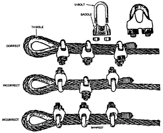
END FITTINGS Some end fittings that are easily and quickly changed are wire rope clips, clamps, thimbles, wedge sockets, and basket sockets. Generally these attachments permit the wire rope to be used with greater flexibility than a more permanent splice would allow. These attachments allow the same wire rope to be made in numerous different arrangements. Wire Rope Clips Wire rope clips are used to make eyes in wire rope, as shown in figure 5-8. The U-shaped part of the clip with the threaded ends is called the U-bolt; the other
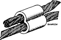
Figure 5-8.-Wire rope clips part is called the saddle. The saddle is stamped with the diameter of the wire rope that the clip will fit. Always place a clip with the U-bolt on the bitter (dead) end, not on the standing part of the wire rope. When clips are attached incorrectly, the standing part (live end) of the wire rope will be distorted or have smashed spots. A rule of thumb to remember when attaching a wire rope clip is to "NEVER saddle a dead horse." Two simple formulas for figuring the number of wire rope clips needed are as follows: 3 x wire rope diameter+ 1 = Number of clips 6 x wire rope diameter= Spacing between clips Another type of wire rope clip is the twin-base clip, often referred to as the universal or two clamp (fig. 5-9). Both parts of this clip are shaped to fit the wire rope; therefore, the clip cannot be attached incorrectly. The twin-base clip allows a clear 360-degree swing with the wrench when the nuts are being tightened. Wire Rope Clamps Wire rope clamps (fig. 5-10) are used to make an eye in the rope with or without a thimble; however, a clamp is normally used without a thimble. The eye will have approximately 90 percent of the strength of the rope. The two end collars should be tightened with wrenches to force the wire rope clamp to a good, snug fit. This squeezes the rope securely against each other. Thimble When an eye is made in a wire rope, a metal fitting, called a thimble, is usually placed in the eye (fig. 5-8). The thimble protects the eye against wear. Wire rope eyes with thimbles and wire rope clips can hold approximately 80 percent of the wire rope strength.
Figure 5-9.-Twin-base wire rope clip.
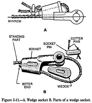
Figure 5-10.-Wire rope. After the eye made with clips has been strained, the nuts on the clips must be retightened. Checks should be made now and then for tightness or damage to the rope cause by the clips. Wedge Socket A wedge socket end fitting (fig. 5-11) is used in situations that require the fitting to be changed frequently. For example, the attachment used most often to attach dead ends of wire ropes to pad eyes, or like fittings, on cranes and earthmoving equipment is the wedge socket. The socket is applied to the bitter end of the wire rope. Fabricated in two parts, the wedge socket has a tapered opening for the wire rope and a small wedge to fit into the tapered socket. The loop of wire rope must be installed in the wedge socket, so the standing part of the wire rope will form a nearly direct line to the clevis pin of the fitting. When a wedge socket is assembled correctly, it tightens as a load is placed on the wire rope.
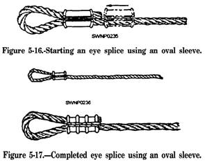
NOTE: The wedge socket efficiency is approximately two thirds of the breaking strength of the wire rope due to the crushing action of the wedge. Basket Socket A basket socket is normally attached to the end of the rope with either molten zinc or babbitt metal; therefore, it is a permanent end fitting. In all circumstances, dry or poured, the wire rope should lead from the socket in line with the axis of the socket. DRY METHOD.- The basket socket can also& fabricated by the dry method (fig. 5- 12) when facilities are not available to make a poured fitting; however, its strength will be reduced to approximately one sixth of that of a poured zinc connection. POURED METHOD.-- The poured basket socket (fig. 5-13) is the preferred method of basket socket assembly. Properly fabricated, it is as strong as the rope itself, and when tested to destruction, a wire rope will break before it will pull out of the socket. When molten lead is used vice zinc, the strength of the connection must be approximate] y three fourths of the strength of a zinc connection Permanent eyes in wire rope slings can also be made in 3/8- to 5/8-inch (9.5 to 15.9-mm) wire rope by using the nicopress portable hydraulic splicing tool and oval sleeves. The nicopress portable splicing tool (fig. 5-14) consists of a hand-operated hydraulic pump connected to a ram head assembly. Included as a part of the tool kit are interchangeable compression dies for wire sizes 3/8, 7/16, 1/2, 9/16, and 5/8 inch (9.5, 11.1, 12.7, 14.3, and 15.9 mm). The dies are in machined halves with a groove size to match the oval sleeve and the wire rope being spliced. The oval sleeves (fig. 5-15) are available in plain copper or zinc-plated copper. To make an eye splice, pick an oval sleeve equal to the size of the wire rope being spliced. Slide the sleeve over the bitter end of the length of rope, then form an eye and pass the bitter end through the end again (fig. 5-16). Next, place the lower half of the compression die in the ram head assembly. Place the oval sleeve in this lower half and drop in the upper half of the die. Fully insert the thrust pin that is used to hold the dies in place when making the swage. Start pumping the handle and continue to do so until the dies meet. At this time the overload valve will pop off, and a 100-percent efficient splice is formed (fig. 5-17). Retract the plunger and remove the swaged splice.
Figure 5-12.-Attaching a basket socket by the dry method.
Figure 5-13.-Attaching a basket socket by the pouring method.
Figure 5-14.-Nicopress portable splicing tool.
Figure 5-15.-Oval sleeve. Check the swage with the gauge supplied in each die set (fig. 5-18). This process represents a savings in time over the eye formed by using wire rope clips.
Additionally, lap splices can be made with nicopress oval sleeves (fig. 5-19). Usually, two sleeves are needed to create a full-strength splice. A short
Figure 5-18.-Swage gauge.
Figure 5-19.-Lap splice using a nicopress oval sleeve. space should be maintained between the two sleeves, as shown. The lap splice should be tested before being used. |
|
Privacy Statement - Press Release - Copyright Information. - Contact Us - Support Integrated Publishing |