 |
||
|
|
||
| |||||||||||||||
|
|
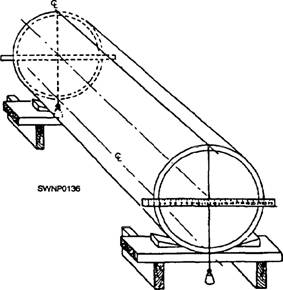
TEMPLATE FOR TWO-PIECE TURN The fact that a length of pipe with square ends can be fabricated by wrapping a rectangular section of plate into a cylindrical form makes available a method (known as parallel forms) of developing pipe surfaces, and hence developing the lines of intersection between
Figure 3-43.-Locating the top and the bottom center lines.
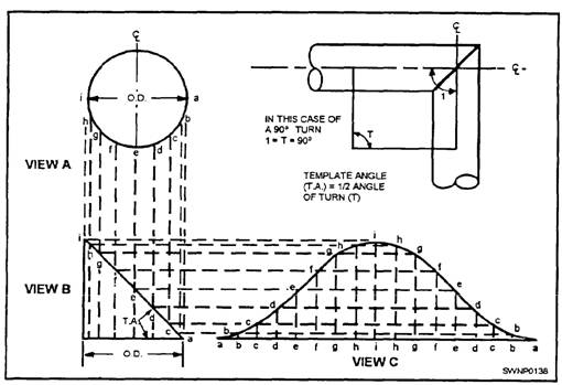
Figure 3-44.-Folding a tip of paper for use in quartering pipe. pipe walls. Based on this principle, wraparound templates can be made for marking all manner of pipe fittings for cutting preparatory to welding. The development of a template is done in practice by dividing the circumference (in the end view) of the pipe into a specific number of equal sections. These sections are then projected onto the side view of the desired pipe section. The lengths of the various segments that make up the pipe wall may then be laid out, evenly spaced, on a base line. This line is, in effect, the unwrapped circumference (fig. 3-45). If the template developed in figure 3-45, view C, is wrapped around the pipe with the base line square with the pipe, the curved line, a-b-c-d-e-f-, and so forth, will locate the position for cutting to make a 90-degree, two-piece turn. Draw a circle (fig. 3-45, view A) equal to the outside diameter of the pipe and divide half of it into equal sections. The more sections, the more accurate the final result will be. Perpendicular to the centerline and bisected by it, draw line AI equal to the O.D. (view B). To this line, construct the template angle (TA) equal to one half of the angle of turn, or, in this case, 45 degrees. Draw lines parallel to the centerline from points a, b, c, and so forth, on the circle and mark the points where these lines intersect line a-i with corresponding letters. As an extension of AI but a little distance from it, draw a straight line equal to the pipe circumference or that of the circle in view A. This line (view C) should then be divided into twice as many equal spaces as the semicircle, a-b-c-, and so forth, and lettered as shown. Perpendiculars should then be erected from these points. Their intersections with lines drawn from the points on a-i in view B, parallel to the base line in view C, determine the curve of the template. SIMPLE MITER TURN After quartering the pipe, proceed to make a simple miter turn. Locate the center of the cut (fig. 3-46, point c) in the general location where the cut is to be made. Use a wraparound to make line a-b completely around the pipe at right angles to the center
Figure 3-45.-Principles of template layout.
Figure 3-46.-Simple miter turn. and quarter lines. This establishes a base line for further layout work. When you are measuring, treat the surface of the pipe as if it were a flat surface. Use a flat-steel rule or tape, which will lie against the surface without kinks, even though it is forced to follow the contour of the pipe. These angles can also be checked for accuracy by sighting with the square. Use the protractor and square to determine the proper cutback for the desired angle of the miter turn. Start with the protractor scale set at zero so that the flat surface of the protractor and the blade are parallel. You can now set the protractor for the number of degrees desired. After you have the correct setting, lock the blade. Place the protractor on the square with the bottom blade on the outside diameter of the pipe. Now read up to the cutback on the vertical blade of the square. You must be sure that the flat surface of the protractor is flush against the blade of the square (fig. 3-47). The outside radius of the pipe should have been determined during the quartering operation. After you have obtained the cutback measurement, mark one half of this measurement off along the center line on top of the pipe. From the opposite side of the base line, measure off the same
Figure 3-47.-Finding the cutback. distance along the bottom quarter line. Make punch marks with the center punch on each side of the line, along the side quarter lines. These marks will make it easy to align the pipe for welding after the joint is cut. Use the spring steel wraparound and pull the loop to the cutback point. Next, draw a chalk line over the top half of the pipe through the first cutback point. (NOTE: Do not allow the wraparound to twist or kink, and hold the chalk at a right angle to the wraparound while marking the pipe.) Now roll the pipe one-half turn and mark a chalk line in the same way around the bottom half of the pipe. |
|
Privacy Statement - Press Release - Copyright Information. - Contact Us - Support Integrated Publishing |