 |
||
|
|
||
| |||||||||||||||
|
|
ANCHOR BOLTS Anchor bolts (fig. 3-6) are cast into the concrete foundation. They are designed to hold the column bearing plates, which are the first members of a steel frame placed into position. These anchor bolts must be positioned very carefully so that the bearing plates will be lined up accurately. BEARING PLATES The column bearing plates are steel plates of various thicknesses in which holes have been either drilled or cut with an oxygas torch to receive the
Figure 3-6.-Anchor bolts. Table 3-1.-Plate, Bar, Strip, and Sheet designation
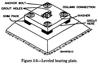
anchor bolts (fig. 3-7). The holes should be slightly larger than the bolts so that some lateral adjustment of the bearing plate is possible. The angle connections, by which the columns are attached to the bearing plates, are bolted or welded in place according to the size of the column, as shown in figure 3-8. After the bearing plate has been placed into position, shim packs are set under the four comers of each bearing plate as each is installed over the anchor bolts, as shown in figure 3-9. `The shim packs are 3- to 4-inch metal squares of a thickness ranging from 1 1/6 to 3/4 inch, which are used to bring all the bearing
Figure 3-8.-Typical column to baseplate connections.
plates to the correct level and to level each bearing plate on its own base. The bearing plates are first leveled individually by adjusting the thickness of the shim packs. This operation may be accomplished by using a 2-foot level around the top of the bearing plate perimeter and diagonally across the bearing plate. Upon completion of the leveling operation, all bearing plates must be brought either up to or down to the grade level required by the structure being erected All bearing plates must be lined up in all directions with each other. This may be accomplished by using a surveying instrument called a builder's level. String lines may be set up along the edges and tops of the bearing plates by spanning the bearing plates around the perimeter of the structure, making a grid network of string lines connecting all the bearing plates. After all the bearing plates have been set and aligned, the space between the bearing plate and the top of the concrete footing or slab must be filled with a hard, nonshrinking, compact substance called GROUT. (See fig. 3-9.) When the grout has hardened the next step is the erection of the columns. COLUMNS Wide flange members, as nearly square in cross section as possible, are most often used for columns. Large diameter pipe is also used frequentl y (fig. 3-10), even though pipe columns often present connecting difficulties when you are attaching other members. Columns may also be fabricated by welding or bolting a number of other rolled shapes, usually angles and plates, as shown in figure 3-11. If the structure is more than one story high, it may be necessary to splice one column member on top of another. If this is required, column lengths should be
Figure 3-10.-Girder span on pipe columns.
Figure 3-11.-Built-up column section. such that the joints or splices are 1 1/2 to 2 feet above the second and succeeding story levels. This will ensure that the splice connections are situated well above the girder or beam connections so that they do not interfere with other second story work. Column splices are joined together by splice plates which are bolted, riveted, or welded to the column flanges, or in special cases, to the webs as well. If the members are the same size, it is common practice to butt one end directly to the other and fasten the splice plates over the joint, as illustrated in figure 3-12. When the column size is reduced at the joint, a plate is used between the two ends to provide bearing, and filler plates are used between the splice plates and the smaller column flanges (fig. 3-13). GIRDERS Girders are the primary horizontal members of a steel frame structure. They span from column to
Figure 3-12.-Column splice with no size change.
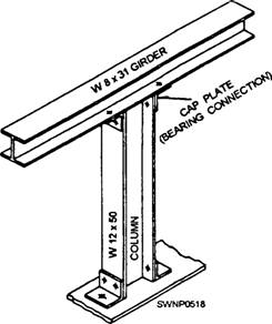
column and are usually connected on top of the columns with CAP PLATES (bearing connections), as shown in figure 3-14. An alternate method is the seated connection (fig. 3-15). The girder is attached to the flange of the column using angles, with one leg extended along the girder flange and the other against the column. The function of the girders is to support the intermediate floor beams.
Figure 3-14.-Girder span on a wide flange column.
Figure 3-15.-Seated connections. BEAMS Beams are generally smaller than girders and are usually connected to girders as intermediate members or to columns. Beam connections at a column are similar to the seated girder-to-column connection. Beams are used generally to carry floor loads and transfer those loads to the girders as vertical loads. Since beams are usually not as deep as girders, there are several alternative methods of framing one into the other. The simplest method is to frame the beam between the top and bottom flanges on the girder, as shown in figure 3-16. If it is required that the top or bottom flanges of the girders and beams be flush, it is necessary to cut away (cope) a portion of the upper or lower beam flange, as illustrated in figure 3-17.
|
|
Privacy Statement - Press Release - Copyright Information. - Contact Us - Support Integrated Publishing |