 |
||
|
|
||
|
Page Title:
CHAPTER 3 STRUCTURAL STEEL TERMS / LAYOUT AND FABRICATION OF STEEL AND PIPE |
||
| |||||||||||||||
|
|
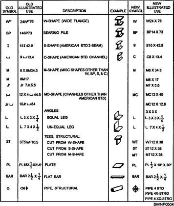
CHAPTER 3 STRUCTURAL STEEL TERMS / LAYOUT AND FABRICATION OF STEEL AND PIPE Structural steel is one of the basic materials used in the construction of frames for most industrial buildings, bridges, and advanced base structures. Therefore, you, as a Seabee Steelworker, must have a thorough knowledge of various steel structural members. Additionally, it is necessary before any structural steel is fabricated or erected, a plan of action and sequence of events be set up. The plans, sequences, and required materials are predetermined by the engineering section of a unit and are then drawn up as a set of blueprints. This chapter describes the terminology applied to structural steel members, the use of these members, the methods by which they are connected, and the basic sequence of events which occurs during erection. STRUCTURAL STEEL MEMBERS Your work will require the use of various structural members made up of standard structural shapes manufactured in a wide variety of shapes of cross sections and sizes. Figure 3-1 shows many of these various shapes. The three most common types of structural members are the W-shape (wide flange), the S-shape (American Standard I-beam), and the C-shape (American Standard channel). These three types are identified by the nominal depth, in inches, along the web and the weight per foot of length, in pounds. As an example, a W 12 x 27 indicates a W-shape (wide flange) with a web 12 inches deep and a weight of 27 pounds per linear foot. Figure 3-2 shows the cross-sectional views of the W-, S-, and C-shapes. The difference between the W-shape and
Figure 3-1.-Structural shapes and designations.
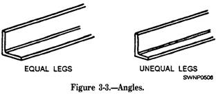
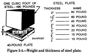
Figure 3-2.-Structural shapes. the S-shape is in the design of the inner surfaces of the flange. The W-shape has parallel inner and outer flange surfaces with a constant thickness, while the S-shape has a slope of approximately 17' on the inner flange surfaces. The C-shape is similar to the S-shape in that its inner flange surface is also sloped approximately 17'. The W-SHAPE is a structural member whose cross section forms the letter H and is the most widely used structural member. It is designed so that its flanges provide strength in a horizontal plane, while the web gives strength in a vertical plane. W-shapes are used as beams, columns, truss members, and in other load-bearing applications. The BEARING PILE (HP-shape) is almost identical to the W-shape. The only difference is that the flange thickness and web thickness of the bearing pile are equal, whereas the W-shape has different web and flange thicknesses. The S-SHAPE (American Standard I-beam) is distinguished by its cross section being shaped like the letter I. S-shapes are used less frequently than W-shapes since the S-shapes possess less strength and are less adaptable than W-shapes. The C-SHAPE (American Standard channel) has a cross section somewhat similar to the letter C. It is especially useful in locations where a single flat face without outstanding flanges on one side is required. The C-shape is not very efficient for a beam or column when used alone. However, efficient built-up members may be constructed of channels assembled together with other structural shapes and connected by rivets or welds. An ANGLE is a structural shape whose cross section resembles the letter L. Two types, as illustrated in figure 3-3, are commonly used: an equal-leg angle and an unequal-leg angle. The angle is identified by the dimension and thickness of its legs; for example, angle 6 inches x 4 inches x 1/2 inch. The dimension of the legs should be obtained by measuring along the outside of the backs of the legs. When an angle has unequal legs, the dimension of the wider leg is given first, as in the example just cited. The third dimension applies to the thickness of the legs, which al ways have equal thickness. Angles may be used in combinations of two or four to form main members. A single angle may also be used to connect main parts together. Steel PLATE is a structural shape whose cross section is in the form of a flat rectangle. Generally, a main point to remember about plate is that it has a width of greater than 8 inches and a thickness of 1/4 inch or greater. Plates are generally used as connections between other structural members or as component parts of built-up structural members. Plates cut to specific sizes may be obtained in widths ranging from 8 inches to 120 inches or more, and in various thicknesses. The edges of these plates may be cut by shears (sheared plates) or be rolled square (universal mill plates). Plates frequently are referred to by their thickness and width in inches, as plate 1/2 inch x 24 inches. The length in all cases is given in inches. Note in figure 3-4 that 1 cubic foot of steel weighs 490 pounds. his weight divided by 12 gives you 40.8, which is the weight (in pounds) of a steel plate 1 foot square and 1 inch thick The fractional portion is normally dropped and 1-inch plate is called a 40-pound plate. In practice, you may hear plate referred to by its approximate weight per square foot for a specified thickness. An example is 20-pound plate, which indicates a 1/2-inch plate. (See figure 3-4.) The designations generally used for flat steel have been established by the American Iron and Steel Institute (AISI). Flat steel is designated as bar, strip,
sheet, or plate, according to the thickness of the material, the width of the material, and (to some extent) the rolling process to which it was subjected. Table 3-1 shows the designations usually used for hot-rolled carbon steels. These terms are somewhat flexible and in some cases may overlap. The structural shape referred to as a BAR has a width of 8 inches or less and a thickness greater than 3/16 of an inch. The edges of bars usually are rolled square, like universal mill plates. The dimensions are expressed in a similar manner as that for plates; for instance, bar 6 inches x 1/2 inch. Bars are available in a variety of cross-sectional shapes-round, hexagonal, octagonal, square, and flat. Three different shapes are illustrated in figure 3-5. Both squares and rounds are commonly used as bracing members of light structures. Their dimensions, in inches, apply to the side of the square or the diameter of the round. Now that you have been introduced to the various structural members used in steel construction, let us develop a theoretical building frame from where you, the Steelworker, would start on a project after all the earthwork and footings or slab have been completed. Remember this sequence is theoretical and may vary
Figure 3-5.-Bars. somewhat, depending on the type of structure being erected. |
|
Privacy Statement - Press Release - Copyright Information. - Contact Us - Support Integrated Publishing |