 |
||
|
|
||
| |||||||||||||||
|
|
JOINING AND INSTALLING SHEET-METAL DUCT After the sheet metal has been cut and formed, it has to be joined together. Most sheet-metal seams are locked or riveted but some will be joined by torch brazing or soldering. Lock seams are made primarily by the forming processes that have already been given.
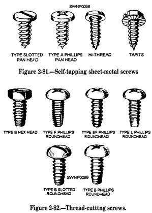
Figure 2-80.-Wire notch in a cylindrical layout. Torch brazing and soldering are discussed in Steelworker, volume 1, chapter 6. This section deals only with joining sheet-metal seams by either metal screws or rivets. METAL SCREWS Different types of metal screws are available for sheet-metal work. The most common type in use is the MACHINE SCREW. Machine screws are normally made of brass or steel. They will have either a flathead or a roundhead and are identified by their number size, threads per inch, and length; for example, a 6 by 32 by 1 inch screw indicates a number 6 screw with 32 threads per inch and 1 inch in length. SELF-TAPPING SHEET-METAL SCREWS are another common type of screw. Most screws of this type will be galvanized and are identified by their number size and length. These screws form a thread as they are driven (fig. 2-81), as the name implies. THREAD-CUTTING SCREWS (fig. 2-82) are different from self-tapping screws in that they actually cut threads in the metal. They are hardened and are used to fasten nonferrous metals and join heavy gauge sheet metal.
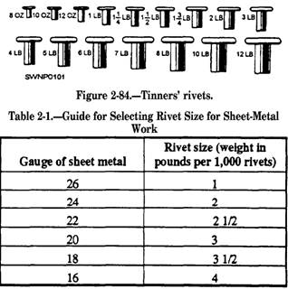
DRIVE SCREWS (fig. 2-83) are simply hammered into a drilled or punched hole of the proper size to make a permanent fastening. RIVETS Rivets are available in many different materials, sizes, and types. Rivets, made of steel, copper, brass, and aluminum, are widely used. Rivets should be the same material as the sheet metal that they join. TINNERS' RIVETS of the kind shown in figure 2-84 are used in sheet-metal work more than any other type of rivet. Tinners' rivets vary in size from the 8-ounce rivet to the 16-pound rivet. This size designation signifies the weight of 1,000 rivets. If 1,000 rivets weigh 8 ounces, each rivet is called an 8-ounce rivet. As the weight per 1,000 rivets increases, the diameter and length of the rivets also increase. For example, the 8-ounce rivet has a diameter of 0.089 inch and a length of 5/32 inch, while the 12-pound rivet has a diameter of 0.259 inch and a length of 1/2 inch. For special jobs that require fastening several layers of metal together, special rivets with extra, long shanks are used. Table 2-1 is a guide for selecting rivets of the proper size for sheet-metal work.
When you are joining sheet metal that is greater than two thicknesses, remember that the shank of the rivet should extend 1 1/2 times the diameter of the rivet. This will give you adequate metal to form the head. Rivet spacing is given on the blueprint or drawing you are working from. If the spacing is not given, space the rivets according to the service conditions the seam must withstand. For example, if the seam must be watertight, you will need more rivets per inch than is required for a seam that does not have to be watertight. No matter how far apart the rivets are, there must be a distance of 2 1/2 times the rivet diameter between the rivets and the edge of the sheet. This distance is measured from the center of the rivet holes to the edge of the sheet.
Figure 2-85.-Hand punch. After you have determined the size and spacing of the rivets, mark the location of the centers of the rivet holes. Then make the holes by punching or by drilling. If the holes are located near the edge of the sheet, a hand punch, similar to the one shown in figure 2-85, can be used to punch the holes. If the holes are farther away from the edge, you can use a deep-threaded punch (either hand operated or power driven) or you can drill the holes. The hole must be slightly larger than the diameter of the rivet to provide a slight clearance. Riveting involves three operations-drawing, upsetting, and heading (fig. 2-86). A rivet set and a riveting hammer are used to perform these operations. The method for riveting sheet metal follows: 1. Select a rivet set that has a hole slightly larger than the diameter of the rivet. 2. Insert the rivets in the holes and rest the sheets to be joined on a stake or on a solid bench top with the rivet heads against the stake or bench top. 3. Draw the sheets together by placing the deep hole of the rivet set over the rivet and striking the head of the set with a riveting hammer. Use a light hammer for small rivets, a heavier hammer for larger rivets. 4. When the sheets have been properly drawn together, remove the rivet set. Strike the end of the rivet LIGHTLY with the riveting hammer to upset the end of the rivet. Do not strike too hard a blow, as this would distort the metal around the rivet hole. 5. Place the heading die (dished part) of the rivet set over the upset end of the rivet and form the head. One or two hammer blows on the head of the rivet set will be enough to form the head on the rivet.
Figure 2-86.-Drawing, upsetting, and heading a rivet.
Figure 2-87.-Correct and incorrect riveting. A correctly drawn, upset, and headed rivet is shown in the top part of figure 2-87. The lower part of this figure shows the results of incorrect riveting. An addition to sheet-metal rivets are the pop rivets shown in figure 2-88. These pop rivets are high-strength, precision-made, hollow rivets assembled on a solid mandrel that forms an integral part of the rivet. They are especially useful for blind fastening-where there is limited or no access to the reverse side of the work.
Figure 2-88.-Pop rivets. Pop rivets provide simplicity and versatility. `hey are simple and easy to use in complicated installations. Expensive equipment or skilled operators are not required. Just drill a hole, insert, and set the pop rivet from the same side, and high riveting quality and strength are easily and quickly accomplished. Two basic designs of pop rivets are used: closed end and open end. The closed-end type fills the need for blind rivets that seal as they are set. They are gastight and liquidtight, and like the open-end type, they are installed and set from the same side. As the rivet sets, a high degree of radial expansion is generated in the rivet body, providing effective hole-filing qualities. The open-end type of pop rivet resembles a hollow rivet from the outside. Because the mandrel head stays in the rivet body, the mandrel stem seals to a certain degree, but it is not liquidtight. Figure 2-89 shows two of the tools used for setting the pop rivets. These tools are lightweight and very easily used. For example, when using the small hand tool, you need only to insert the mandrel of the rivet in the nosepiece, squeeze the handle (usually three times), and the rivet is set. To operate the scissors-type tool, fully extend the lever linkage or gatelike mechanism and insert the rivet mandrel into the nosepiece of the tool. Insert the rivet into the piece being riveted. Apply firm pressure to the tool, ensuring that the nosepiece remains in close contact with the rivet head. Closing the lever linkage retracts the gripping mechanism, which withdraws the mandrel. The rivet is set when the mandrel head breaks.
Figure 2-89.-Pop rivet toots. Before inserting another rivet in the tool, be sure that the broken mandrel has been ejected from the tool. This can be done by fully extending the lever linkage and allowing the mandrel to fall clear. The scissors or expandable type of tool is unique because it can reach hard-to-get-at areas and can set the rivets with ease. This tool is particular] y useful for installing ventilation ducting. |
|
Privacy Statement - Press Release - Copyright Information. - Contact Us - Support Integrated Publishing |