 |
||
|
|
||
|
Page Title:
FABRICATION OF EDGES, JOINTS, SEAMS, AND NOTCHES |
||
| |||||||||||||||
|
|
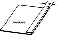
FABRICATION OF EDGES, JOINTS, SEAMS, AND NOTCHES There are numerous types of edges, joints, seams, and notches used to join sheet-metal work. We will discuss those that are most often used. Edges Edges are formed to enhance the appearance of the work, to strengthen the piece, and to eliminate the cutting hazard of the raw edge. The kind of edge that you use on any job will be determined by the purpose, by the sire, and by the strength of the edge needed. The SINGLE-HEM EDGE is shown in figure 2-54. This edge can be made in any width. In general, the heavier the metal, the wider the hem is made. The allowance for the hem is equal to its width (W in fig. 2-54).
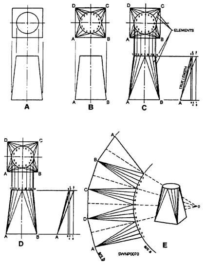
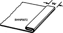
Figure 2-53.-Traingular development of a transition piece. The DOUBLE-HEM EDGE (fig. 2-55) is used when added strength is needed and when a smooth edge is required inside as well as outside. The allowance for the double-hem edge is twice the width of the hem.
Figure 2-54.-Single-hem edge.
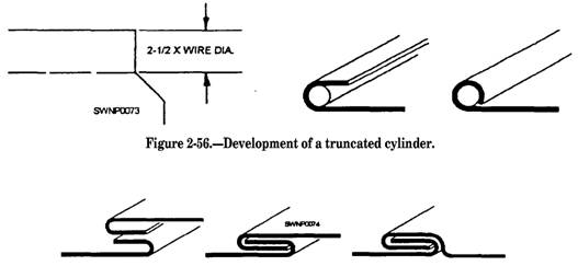
Figure 2-55.-Double-hem edge A WIRE EDGE (fig. 2-56) is often specified in the plans, Objects, such as ice-cube trays, funnels, garbage pails, and other articles, formed from sheet metal are fabricated with wire edges to strengthen and stiffen the jobs and to eliminate sharp edges, The
Figure 2-57.-Making a grooved seam joint.
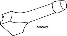
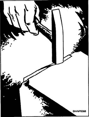
Figure 2-58.-Hand groover.
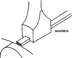
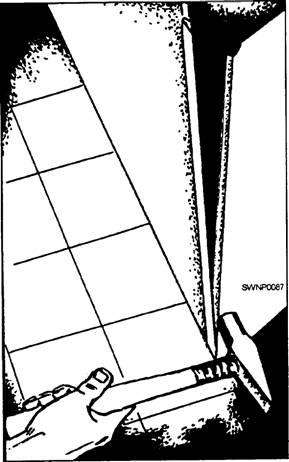
Figure 2-59.-Locking a grooved seam with a hand groover. allowance for a wire edge is 2 1/2 times the diameter of the wire used As an example, you are using wire that has a diameter of 1/8 inch. Multiply 1/8 by 2 1/2 and your answer will be 5/16 inch, which you will allow when laying out sheet metal for making the wire edge. Joints The GROOVED SEAM JOINT (fig. 2-57) is one of the most widely used methods for joining light- and medium-gauge sheet metal. It consists of two folded edges that are locked together with a HAND GROOVER (fig. 2-58). When making a grooved seam on a cylinder, you fit the piece over a stake and lock it with the hand groover (fig. 2-59). The hand groover should be approximately 1/16 inch wider than the seam. Lock the seam by making prick punch indentions about 1/2 inch in from each end of the seam. The CAP STRIP SEAM (fig. 2-60, view A) is often used to assemble air-conditioning and heating ducts. A variation of the joint, the LOCKED CORNER SEAM (fig. 2-60, view B), is widely accepted for the assembly of rectangular shapes.
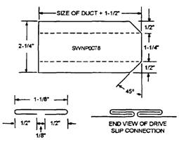
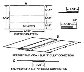
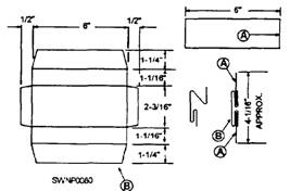
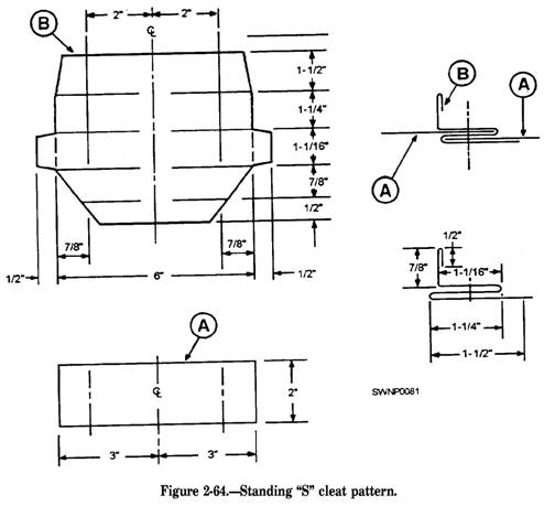
Figure 2-60.-(A) Cap strip seam, (B) Locked corner seam A DRIVE SLIP JOINT is a method of joining two flat sections of metal. Figure 2-61 is the pattern for the drive slip. End notching and dimensions vary with application and area practice on all locks, seams, and edges. "S" joints are used to join two flat surfaces of metal. Primarily these are used to join sections of rectangular duct. These are also used to join panels in air housings and columns. Figure 2-62 shows a flat "S" joint. View A is a pattern for the "S" cleat. View B is a perspective view of the two pieces of metal that form the flat "S" joint. In view C, note the end view of the finished "S" joint. Figure 2-63 shows a double "S" joint. View B is the pattern for the double "S" cleat. View A is one of two pieces of metal to be joined. Note the cross section of a partially formed cleat and also the cross section of the finished double "S" joint. his is a variation of
Figure 2-61.-Drive slip pattern and connections
Figure 2-62.-"S" joint or slip pattern and connections.
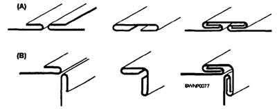
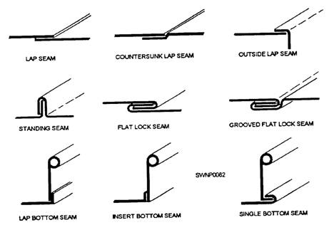
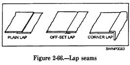
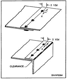
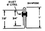
Figure 2-63.-Double "S' joint (cleat) pattern. the simple flat "S" and it does not require an overlap of metals being joined. Figure 2-64 shows a standing "S" joint. View B is the pattern for the standing "S" cleat. View A is one of the two pieces of metal to be joined. Note the cross section of the finished standing "S" cleat and standing "S" joint. Seams Many kinds of seams are used to join sheet-metal sections. Several of the commonly used seams are shown in figure 2-65. When developing the pattern, ensure you add adequate material to the basic dimensions to make the seams. The folds can be made by hand; however, they are made much more easily on a bar folder or brake. The joints can be finished by soldering and/or riveting. When developing sheet-metal patterns, ensure you add sufficient material to the base dimensions to make the seams. Several types of seams used to join sheet-metal sections are discussed in this section. There are three types of lap seams: the PLAIN LAP seam, the OFFSET LAP seam, and the CORNER LAP seam (fig. 2-66). Lap seams can be joined by drilling and riveting, by soldering, or by both riveting and soldering. To figure the allowance for a lap seam, you must first know the diameter of the rivet that you plan to use. The center of the rivet must be set in from the edge a distance of 2 1/2 times its diameter; therefore, the allowance must be five times the diameter of the rivet that you are using. Figure 2-67 shows the procedure for laying out a plain lap and a comer lap for seaming with rivets (d represents the diameter of the rivets). For comer seams, allow an additional one sixteenth of an inch for clearance.
Figure 2-65.-Common sheet-metal seams.
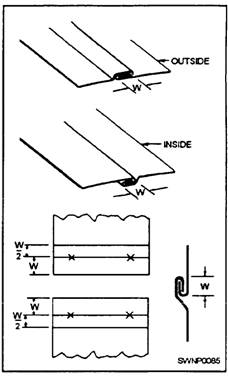
Figure 2-67.-Layout of lap seams for riveting. GROOVED SEAMS are useful in the fabrication of cylindrical shapes. There are two types of grooved seams-the outside grooved seam and the inside grooved seam (fig. 2-68). The allowance for a grooved seam is three times the width (W in fig. 2-68) of the lock, one half of this amount being added to each edge. For example, if you are to have a 1/4-inch grooved seam, 3 x 1/4 = 3/4 inch, or the total allowance; 1/2 of 3/4 inch = 3/8 inch, or the allowance that you are to add to each edge. The PITTSBURGH LOCK SEAM (fig. 2-69) is a comer lock seam. Figure 2-69 shows a cross section of the two pieces of metal to be joined and a cross section of the finished seam. This seam is used as a lengthwise seam at comers of square and rectangular pipes and elbows as well as fittings and ducts. This seam can be made in a brake but it has proved to be so universal in use that special forming machines have been designed and are available. It appears to be quite complicated, but like lap and grooved seams, it
Figure 2-68.-Grooved seams
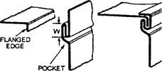
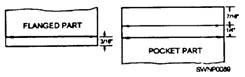
Figure 2-69.-Pittsburgh lock seam. consists of only two pieces. The two parts are the flanged, or single, edge and the pocket that forms the lock The pocket is formed when the flanged edge is inserted into the pocket, and the extended edge is turned over the inserted edge to complete the lock. The method of assembling and locking a Pittsburgh seam is shown in figures 2-70 and 2-71. The allowance for the pocket is W + W + 3/16 inch. W is the width or depth of the pocket. The width of the flanged edge must be less than W. For example, if you are laying out a 1/4-inch Pittsburgh leek seam (fig. 2-72), your total allowance should be 1/4 + 1/4 + 3/16 inch, or 11/16 inch for the edge on which you are laying out the pocket and 3/16 inch on the flanged edge.
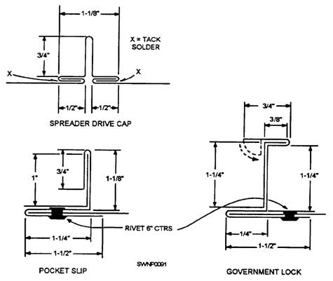
Figure 2-70.-Assembly of a Pittsburgh lock seam STANDING SEAMS are used for joining metals where extra stiffness is needed, such as roofs, air housing, ducts, and so forth. Figure 2-73 is a cross section of the finished standing seam. Dimensions and rivet spacing will vary with application. Standing seams used when stiffening is required are as follows: The SPREADER DRIVE CAP, the POCKET SLIP, and the GOVERNMENT LOCK (fig. 2-74) are seams frequently used in large duct construction where stiffeners are required. The DOVETAIL SEAM is used mainly to join a round pipe/fitting to a flat sheet or duct. This seam can be made watertight by soldering. Figure 2-75 shows the pattern for forming a dovetail seam and an example of its use. Notches Notching is the last but not the least important step to be considered when you are getting ready to lay out
Figure 2-71.-Closing a Pittsburgh lock seam
Figure 2-72.-Layout of a 1/4-inch Pittsburgh lock seam.
Figure 2-73.-Cross section of a standing seam. a job. Before you can mark a notch, you will have to lay out the pattern and add the seams, the laps, or the stiffening edges. If the patterns are not properly notched, you will have trouble when you start forming, assembling, and finishing the job. No definite rule for selecting a notch for a job can be given. But as soon as you can visualize the assembly of the job, you will not have any trouble determining the shape and size of the notch required
Figure 2-74.-Miscellaneous seam.
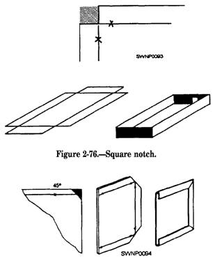
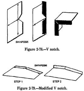
Figure 2-75.-Dovetail lock seam for the job. If the notch is made too large, a hole will be left in the finished job. If the notch is too small or not the proper shape, the metal will overlap and bulge at the seam or edge. Do not concern yourself too much if your first notches do not come out as you expected-practice and experience will dictate size and shape. A SQUARE NOTCH (fig. 2-76) is likely the first you will make. It is the kind you make in your layout of a box or drip pan and is used to eliminate surplus material This type of notch will result in butt comers. Take a look around the shop to see just how many different kinds of notches you can see in the sheet-metal shapes. SLANT NOTCHES are cut at a 45-degree angle across the comer when a single hem is to meet at a 90-degree angle. Figure 2-77 shows the steps in forming a slant notch. A V NOTCH is used for seaming ends of boxes. You will also use a full V notch when you have to construct a bracket with a toed-in flange or for similar construction. The full V is shown in figure 2-78. When you are making an inside flange on an angle of less than 90 degrees, you will have to use a modification of the full V notch to get flush joints. The angle of the notch will depend upon the bend angle. A modified V notch is shown in figure 2-79.
Figure 2-77.-Slant notch.
A WIRE NOTCH is a notch used with a wire edge. Its depth from the edge of the pattern will be one wire diameter more than the depth of the allowance for the wire edge (2 1/2 d), or in other words, 3 1/2 times the diameter of the wire (3 1/2 d). Its width is equal to 1 1/2 times the width of the seam (1 1/2 w). That portion of the notch next to the wire edge will be straight. The shape of the notch on the seam will depend on the type of seam used, which, in figure 2-80, is 45 degrees for a grooved seam. Most of your work will require more than one type of notch, as shown in figure 2-80, where a wire notch was used in the forming of a cylindrical shape joined by a grooved seam. In such a layout, you will have to notch for the wire edge and seam. |
|
Privacy Statement - Press Release - Copyright Information. - Contact Us - Support Integrated Publishing |