 |
||
|
|
||
| |||||||||||||||
|
|
STARTING THE ARC Two basic methods are used for starting the arc: the STRIKING or BRUSHING method (fig. 7-10) and the
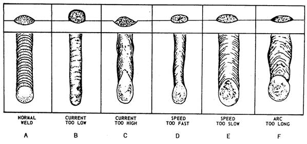
Figure 7-11.-Tapping method of starting the arc. TAPPING method (fig. 7-11). In either method, the arc is started by short circuiting the welding current between the electrode and the work surface. The surge of high current causes the end of the electrode and a small spot on the base metal beneath the electrode to melt instantly. In the STRIKING or BRUSHING method, the electrode is brought down to the work with a lateral motion similar to striking a match. As soon as the electrode touches the work surface, it must be raised to establish the arc (fig. 7-10). The arc length or gap between the end of the electrode and the work should be equal to the diameter of the electrode. When the proper arc length is obtained, it produces a sharp, crackling sound. In the TAPPING method, you hold the electrode in a vertical position to the surface of the work. The arc is started by tapping or bouncing it on the work surface and then raising it to a distance equal to the diameter of the electrode (fig. 7-11). When the proper length of arc is established, a sharp, crackling sound is heard. When the electrode is withdrawn too slowly with either of the starting methods described above, it will stick or freeze to the plate or base metal. If this occurs, you can usually free the electrode by a quick sideways wrist motion to snap the end of the electrode from the plate. If this method fails, immediately release the electrode from the holder or shutoff the welding machine. Use alight blow with a chipping hammer or a chisel to free the electrode from the base metal. CAUTION NEVER remove your helmet or the shield from your eyes as long as there is any possibility that the electrode could produce an arc. After you strike the arc, the end of the electrode melts and flows into the molten crater of the base metal. To compensate for this loss of metal, you must adjust the length of the arc. Unless you keep moving the electrode closer to the base metal, the length of the arc will increase. An arc that is too long will have a humming type of sound. One that is too short makes a popping noise. When the electrode is fed down to the plate and along the surface at a constant rate, a bead of metal is deposited or welded onto the surface of the base metal. After striking the arc, hold it for a short time at the starting point to ensure good fusion and crater deposition. Good arc welding depends upon the control of the motion of the electrode along the surface of the base metal. Setting the Current The amount of current used during a welding operation depends primarily upon the diameter of the electrode. As a rule, higher currents and larger diameter electrodes are better for welding in the flat position than the vertical or overhead position. Manufacturers of electrodes usually specify a current range for each type and size of electrode; this information is normally found on the face of the electrode container. Since most recommended current settings are only approximate, final current settings and adjustments need to be made during the welding operation. For example, when the recommended current range for an electrode is 90-100 amperes, the usual practice is to set the controls midway between the two limits, or at 95 amperes. After starting the weld, make your final adjustments by either increasing or decreasing the current. When the current is too high, the electrode melts faster and the molten puddle will be excessively large and irregular. High current also leaves a groove in the base metal along both sides of the weld. This is called undercutting, and an example is shown in figure 7-12, view C. With current that is too low, there is not enough heat to melt the base metal and the molten pool will be too small. The result is poor fusion and a irregular shaped deposit that piles up, as shown in figure 7-12, view B. This piling up of molten metal is called overlap. The molten metal from the electrode lays on the work without penetrating the base metal. Both undercutting and overlapping result in poor welds, as shown in figure 7-13. When the electrode, current, and polarity are correct, a good arc produces a sharp, crackling sound. When any of these conditions are incorrect, the arc produces a steady, hissing sound, such as steam escaping.
Figure 7-12.-Comparison chart of welds.
Figure 7-13.-Undercuts and overlaps in welding. Length of Are When an arc is too long, the metal melts off the electrode in large globules and the arc may break frequently. This produces a wide, spattered, and irregular deposit with insufficient fusion between the base metal and the weld (fig. 7-12, view F). When an arc is too short, it fails to generate enough heat to melt the base metal properly, causes the electrode
Figure 7-14.-Setting the length of an arc. to stick frequently to the base metal, and produces uneven deposits with irregular ripples. The recommended length of the arc is equal to the diameter of the bare end of the electrode, as shown in figure 7-14. The length of the arc depends upon the type of electrode and the type of welding being done; therefore, for smaller diameter electrodes, a shorter arc is necessary than for larger electrodes. Remember: the length of the arc should be about equal to the diameter of the bare electrode except when welding in the vertical or overhead position. In either position, a shorter arc is desirable because it gives better control of the molten puddle and prevents atmospherical impurities from entering the weld.
Electrode Angle The angle at which you hold the electrode greatly affects the shape of the weld bead which is very important in fillet and deep groove welding. The electrode angle consists of two positions: work angle and travel angle. Work angle is the angle from the horizontal measured at right angles to the direction of welding (fig, 7-15). Travel angle is the angle in the direction of welding and may vary from 5 to 30 degrees, depending on the welder's choice and conditions (fig. 7-16). Work angle is especially important in multiple-pass fillet welding. Normally, a small variance of the work angle will not affect the appearance or quality of a weld; however, when undercuts occur in the vertical section of a fillet weld, the angle of the arc should be lowered and the electrode directed more toward the vertical section. Travel Speed Travel speed is the rate at which the electrode travels along a weld seam. The maximum speed of welding depends on the skill of the operator, the position of the weld, the type of electrode, and the required joint penetration. Normally, when the travel speed is too fast, the molten pool cools too quickly, locking in impurities and causing the weld bead to be narrow with pointed ripples, as shown in figure 7-12, view D. On the other hand, if the travel speed is too slow, the metal deposit piles up excessively and the weld is high and wide, as shown in figure 7-12, view E. In most cases, the limiting factor is the highest speed that produces a satisfactory surface appearance of a normal weld, as shown in figure 7-12, view A. Breaking the Arc The most commonly used method to break the arc is to hold the electrode stationary until the crater is filled and then slowly withdraw the electrode. This method reduces the possibilities of crater cracks. Reestablishing the Arc When it becomes necessary to reestablish the are (as in a long weld that requires the use of more than one electrode), the crater must first be cleaned before striking the arc. Strike the tip of the new electrode at the forward (cold) end of the crater and establish an arc. Move the arc backward over the crater, and then move forward again and continue the weld. This procedure fills the crater and prevents porosity and slag inclusions. Peening Peening is a procedure that involves lightly hammering a weld as it cools. This process aids in relieving built-up stresses and preventing surface cracking in the joint area; however, peening should be done with care because excess hammering can work harden and increase stresses in the weld. This condition leads to weld embrittlement and early failure. Some welds are covered by specific codes that prohibit peening so you should check the weld specification before peening. |
|
Privacy Statement - Press Release - Copyright Information. - Contact Us - Support Integrated Publishing |