| Tweet |

Custom Search
|
|
 
|
||
|
CHARACTERISTICS
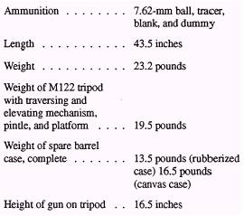
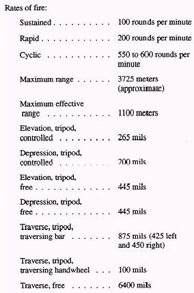
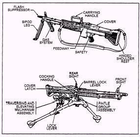
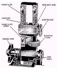
OF THE M60 MACHINE GUN The M60 machine gun is an air-cooled, belt-fed, gas-operated automatic weapon. The weapon features fixed headspace that permits rapid changing of the barrel. Two barrels are issued with each weapon, and an experienced gun crew can change the barrel in a few seconds.) The M60 fires from the open-bolt position. Ammunition is fed into the gun by a disintegrating metallic split-link belt. The gas from the previously fired round provides energy to cock, load, and fire the next round. The bolt must be to the rear before the round can be picked up and fed into the chamber. It fires the standard 7.62-(North Atlantic Treaty Organization) cartridge at a sustained rate of 100 rounds per minute with six to eight rounds per burst, for 10 minutes; then you must change the barrel. On rapid fire, it can deliver up to 200 rounds per minute for 2 minutes before the barrel must be changed. The cyclic rate of fire is 550 to 600 rounds per minute, with a barrel change required every minute. Muzzle velocity is 2,700 feet per second, with a maximum range of 3725 meters. The maximum effective range is 1100 meters. GENERAL DATA The external nomenclature of the M60 machine gun is shown in figure 13-6. The M60 has a front sight permanently affixed to the barrel. The rear sight leaf, as shown in figure 13-7, is mounted on a spring type of dovetail. It can be folded forward horizontally when the gun is to be moved. The range plate on the sight leaf is marked for each 100 meters, from 300 meters to the maximum effective range of 1100 meters. Range changes may be made by using either the slide release or the elevating knob. The slide release is used for making major changes in elevation. The elevating knob is used for fine adjustments, such as those made during zeroing. Four clicks on the elevating knob equal a l-mil change in elevation. The sight is adjustable for windage 5 mils right and left of zero. The windage knob is located on the left side of the sight. One click on the windage knob equals a 1-mil change of deflection. A safety lever is located on the left side of the trigger housing. It has an S (safe) and an F (fire) position. On the S position, the bolt cannot be pulled to the rear or released to go forward. The cocking handle on the right
Figure
13-6.-External nomenclature of the M60 machine gun.
Figure
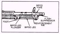
13-7.-The rear sight. side of the gun is used to pull the bolt to the rear. Always remember that the cocking handle must be returned manually to its forward position each time the bolt is manually pulled to the rear. The flash suppressor is affixed to the muzzle of the barrel. The ribs of this suppressor vibrate during firing and dissipate flash and smoke. The M60 can be effectively fired from the integral biped mount (fig. 13-6). The hinged shoulder rest provides support for the rear of the gun. The movable carrying handle provides a method for carrying the gun
Figure
13-8.-Bipod mount.
Figure
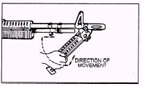
13-9.-Lowering the biped leg.
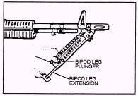
Figure
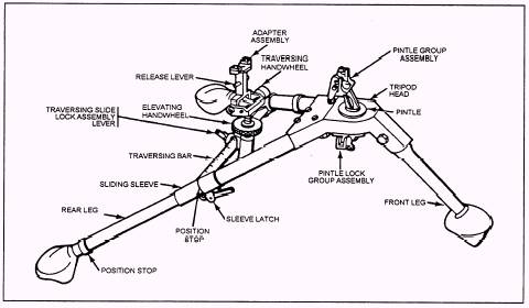
13-10.-Adjusting the biped leg extension to lengthen the leg. short distances and can be positioned out of the gunner's line of sight. The biped mount is an integral part of the barrel group. The biped yoke fits around the barrel and is held in position by the flash suppressor, as shown in figure 13-8. To lower a biped leg, pull it to the rear (compressing the lock spring) and push it downward, as shown in figure 13-9. The leg automatically y locks when in the down position. To lengthen a biped leg, pull down on the foot, as shown in figure 13-10. The biped leg plunger engages a notch in the biped leg extension and holds it in the desired position. To shorten the biped leg, depress the biped leg plunger and push upon the biped foot. The Ml22 tripod mount provides a stable and durable mount for the M60 machine gun. Firing the gun from the tripod permits a high degree of accuracy and control. The Ml22 tripod mount consists of the tripod assembly, the traversing and elevating mechanism, and the pintle and platform group. The tripod mount consists of a tripod head with a pintle bushing and pintle lock, one front and two rear legs, and a traversing bar, as shown in figure 13-11. The traversing bar connects the two rear legs and supports the traversing and elevating mechanism. Engraved on the bar is a scale that is divided into 100-mil major divisions and 13-mil subdivisions, 450 mils to the left and 425 to 430 mils to the right of center. A sliding sleeve
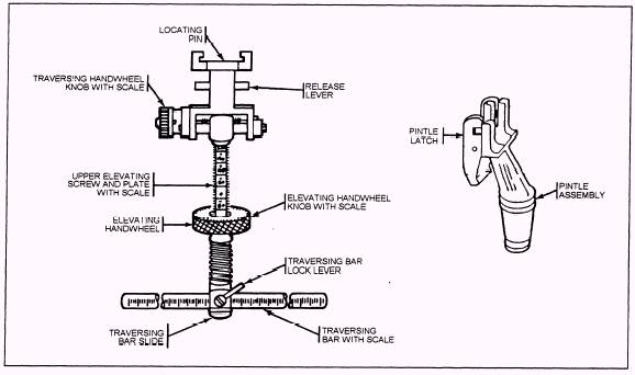
Figure 13-11.-Machine gun tripod mount, M122. Figure 13-12.-Traversing and elevating mechanism, pintle,
and platform group. connects the traversing bar and a rear leg to permit the legs to fold. Position stops are provided to stop the traversing bar in the open or closed positions. The sleeve latch on the right rear leg secures the traversing bar when in the open position. (See fig. 13-11.) The traversing and elevating mechanism shown in figure 13-12 consists of (1) the elevation adapter that connects to the mounting plate on the bottom of the receiver and (2) the traversing handwheel that has a roil-click device built into it. One click equals a l-mil change. Engraved on the traversing handwheel is a scale that is divided into l-mil increments for a total of 25 mils. Use of the traversing mechanism allows the gun to be traversed approximately 100 mils (50 mils right and left of center). The elevating handwheel has a mil-click device built into it. One click equals a 1-mil change. Engraved on the handwheel is a scale divided into 5-mil major divisions and 1-mil subdivisions. The scale is read directly from the indicator. The upper elevating screw has the elevating screw plate, which is graduated into 50-mil increments. There are 200 mils above and 200 mils below the zero mark for a total of 400 mils in elevation change. The traversing slide lock lever allows rapid lateral adjustments along the traversing bar. Readings are taken from the left side of the slide. The pintle and platform group shown in figure 13-12 consist of the gun platform and the pintle, which is secured to the tripod assembly. To mount the gun, (1) lock the pintle and platform group into the pintle bushing, as shown in figure 13-13;
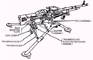
Figure 13-13.-Gun in relation to the tripod. Figure
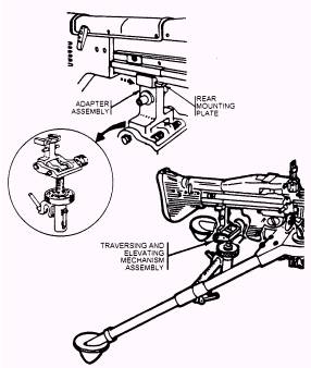
13-14.-Attaching the traversing and elevating mechanism.
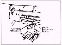
Figure
13-15.-Removing the traversing and elevating mechanism. (2) position the front locating pin (in the forearm assembly) in the front mounting lug; and (3) lower the receiver so the rear locking pin snaps under the platform latch. To attach the traversing and elevating mechanism, take the following steps: (1) mount the gun on the tripod, release the platform lock, and raise the rear of the gun; (2) place the mounting plate recess on the rear of the mounting plate and push it forward, as shown in figure 13-14 (the adapter pin automatically locks into position in the bottom of the mounting plate); and (3) lower the rear of the gun, place the traversing slide (with the traversing slide-lock lever to the rear) on the traversing bar, and lock into position. To remove the traversing and elevating mechanism, release the traversing slide-lock lever and raise the rear of the gun. Pull down on the adapter pin release and pull the mechanism straight back off the mounting plate, as shown in figure 13-15. Return the platform lock to the down position. Stand to the left of the gun and grasp the carrying handle with your left hand. With your right hand, depress the platform latch and raise the rear of the gun slightly, thus removing the rear locking pin from under the platform latch. Place your right hand on the top of the stock, pull the gun slightly to the rear, pushdown on the stock, and lift the gun from the mount. |
 |
|
|
||