| Tweet |

Custom Search
|
|
 
|
||
|
SB-22/PT TELEPHONE SWITCHBOARD The SB-22/PT telephone switchboard shown in figure 11-17 is a lightweight, battery-operated, field switchboard that has 12 interconnecting voice-frequency circuits. The SB-22/PT is normally used to interconnect local-battery telephone circuits, remote-controlled radio circuits, and voice-frequency teletypewriter circuits. Four BA-30 flashlight batteries provide 3 volts of direct current for its operation. The SB-22/PT has a range of 14 to 22 miles. The switchboard unit weighs about 30 pounds. The SB-22/PT consists of four basic parts: the operator's pack (fig. 11-18); the line and trunk pack (fig. 11-19); the accessory kits (fig. 11-20); and the handset-headset (fig. 11-21). Before operating the SB-22/PT switchboard, you should first become familiar with the different controls
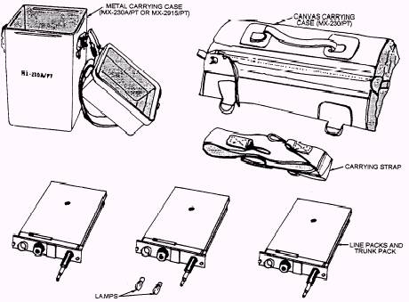
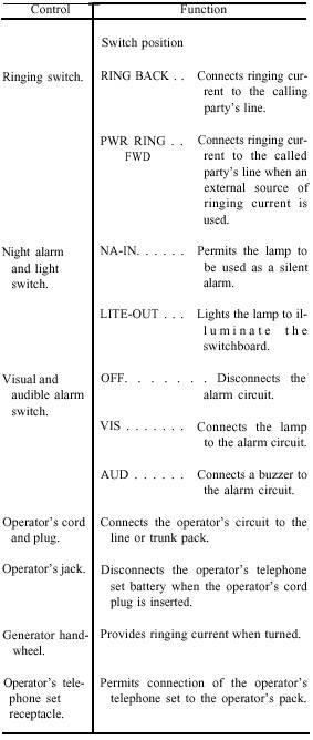
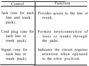
Figure 11-20.-Accessory kits, MX-230/PT, MX-230A/PT, and MX-2915/PT. Figure 11-21.-Handset-headset, H81A/U. Figure 11-22.-Operator's pack control and function. and their functions. Figure 11-22 lists the controls and their functions in operating the OPERATOR'S PACK; figure 11-23 lists the controls and their functions in operating the LINE and TRUCK PACKS. To put the SB-22/PT switchboard into operation, you first put on your HANDSET-HEADSET and
Figure 11-23.-Line and trunk packs control and function. connect it to the switchboard in the following manner: 1. Place the headset (fig. 11-21) over your head so the receiver covers one ear. 2. Position the transmitter directly in front of your mouth. 3. Align the connector (fig. 11-21) on your headset cord with the receptacle on the operator's pack (fig. 11-18). Push it into the connector and turn it to the right so it locks in place. NOTE: The spacing of the lugs around the inside of the connector determines the position of the connector. 4. Clip the PUSH-TO-TALK SWITCH on the handset-headset to the front of your shirt. After inserting the plug of your operating cord into the operator's pack (fig. 11-18), place the push-to-talk switch into any of the positions shown in figure 11-24. When answering the calling party, watch the signals on the front of the line packs (fig. 11-19); the line signals turn from black to white. Follow the procedures below to answer the incoming call (fig. 11-25, view A). 1. Remove the plug of the operator's cord from the operator's jack and insert it into the jack that shows the white line signal (calling party's line signal). 2. Obtain the called party's name or number from the calling party and then proceed to interconnect the parties. When connecting the calling party to the called party (fig. 11-25, view B), pull out the cord in the calling party's line and insert the plug into the called party's line
Figure 11-25A and B.-Steps required to connect local calls through the SB-22/PT
switchboard. Figure 11-25 C and D.-Steps required to connect local calls through the SB-22/PT switchboard. jack (fig. 11-25, view C). Then, signal the called party by turning the hand-ringing generator (fig. 11-18) rapidly for approximately 10 turns. Do NOT operate the RING BACK-PWR RING FWD switch to either position. Wait for the called party to answer. After the called party answers, remove the operator's plug from the called party's jack and insert it into the operator's jack. After the calling and called parties finish talking, both parties should ring off. The ring-off signal causes the calling party's line to turn white. If you should have to challenge the ring-off signal, remove the operator's plug from the operator's jack and insert it into the calling party's jack Ask the parties if they have finished. If no one answers, disconnect the circuit. Remove the operator's plug from the calling party's jack and insert it into the operator's jack. If the calling party disconnects before the called party answers or before the conversation is completed, Figure 11-26.-Installation arrangement for two switchboards. you can ring back the calling party (fig. 11-25, view D). You do this by removing the plug of the operator's cord from the operator's jack on the operator's pack and inserting it into the calling party's jack. Operate the RING BACK-PWR RING FWD switch to the RING BACK, turn the hand-ringing generator rapidly approximately 10 turns. Remove the operator's plug from the calling party's jack and insert it into the operator's jack when both parties answer. If the called party disconnects before the conversation is completed, remove the plug of the operator's cord from the operator's pack and insert it into the jack of the calling party's line jack Operate the hand-ringing generator rapidly about 10 turns. Remove the plug of the operator's cord from the jack of the calling party's line jack and insert it into the operator's jack on the operator's pack after both parties have answered. If you must leave the switchboard, move the visual and audible alarm switch (fig. 11-1 8) from VIS to AUD. The alarm is silent on VIS, but audible on AUD. When the alarm is not required, place the VIS/AUD switch in the OFF position. To operate your switchboard in the dark, pull out on the lamp cap and turn the lamp on. Remember, though, when the lamp is lighting the switchboard, the night alarm cannot be used at the same time. |
||
|
||