| Tweet |

Custom Search
|
|
 
|
||
|
ANTENNA EQUIPMENT RC-292 The RC-292 antenna (fig. 11-12) is an elevated, wide-band, modified ground-plane antenna designed to increase the range of radio sets in the 30 to 76 MHz range. The reception range for the RC-292 is 8 to 36 miles, depending on the type of radio set being used and the terrain. The RC-292 can be used with the AN/PRC-77, AN/PRC-104, AN/GRC-160, and AN/GRA-39.
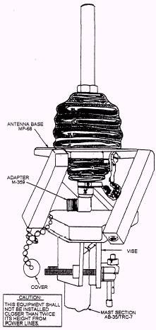
Figure 11-13.-Antenna RC-292 setup. The antenna (fig. 11-13) consists of one vertical radiating element that makes an angle of 140 degrees with the vertical element. Antenna Base MP-68 mounts the four antenna elements and provides for connecting the antenna to the radio set by the CG-107/U. Twelve Mast Sections AB-35/TRC-7, joined together, form the 30-foot mast assembly for elevating above ground. The mast assembly is supported on Mast Base Assembly AB-154/U installed in the baseplate and is held in a vertical position by six guy ropes. The lengths of the antenna elements are adjusted for different frequency ranges by changing the number of mast sections that make up the antenna elements. The swivel stake on which the mast is supported facilitates lowering of the antenna to make such changes. The equipment maybe transported by hand (manually) or by vehicle. When disassembled, the RC-292 should be packed in a canvas roll. The components of the antenna RC-292 are as follows: 1. Antenna Elements. The vertical radiating element and three ground-plane elements consist of one, two, or three Mast Sections AB-21/GR, and one each of
Figure 11-14.-Antenna base MP-68 mounted on mast. Mast Sections AB-22/GR, AB-23/GR, and AB-24/GR. The mast sections are copper plated, painted tubes of high-strength steel that can be screwed together. 2. Antenna Base MP-68. The MP-68 (fig. 11-14) is comprised of a ceramic feed-through insulator, sockets for mounting the antenna elements, an M-359 adapter, and a vise. The feed-through insulator permits the vertical radiating antenna element socket to be connected through the M-359 adapter to the center conductor of the CG-107/U. The three ground-plane sockets and the outer conductor of the CG-107/U connect to the metal framework of the antenna base. The vise enables the antenna base to be clamped to the top of the supporting mast assembly. 3. Mast Section AB-35/TRC-7. Twelve sections are provided for assembling the
30-foot supporting mast assembly. Each section is tubular and has a male and
female end that permit the sections to be fitted together. 4. Mast Base Assembly AB-154/U. This assembly consists of Guy Stake GP101/U attached to a yoke and clevis pin assembly. The lowermost Mast Section Assembly AB-35/TRC7 is placed in the yoke and clevis pin assembly. The yoke and clevis pin arrangement allows the mast assembly to be lowered to the ground by pivoting around the stake. 5. Guy Ropes, Guy Plates, and Guy Stakes. These items hold the mast assembly in a vertical position (fig. 11-13). 6. Reel Rl-28. Three of these reels are provided; two are wound on each of the three reels. 7. Cable Assembly, Radio Frequency Cord CG-107/U. The CG-107/U is a 68-foot length of 50-ohm, solid-dielectric, coaxial radio-frequency (rf) cable, terminated in male Plugs PL-259-A. 8. Adapter M-442. The M-442 consists of an angle bracket provided with Socket SO-259, an insulated lead, and a ground lead that permits the CG-107/U to be easily connected to Radio Sets SCR-508, SCR-528, SCR-608, and SCR-628. 9. Adapter Connector UG-255/U. The UG-255/U is required to adapt the CG-107/U to Receiver-Transmitters RT-66/GRC, RT-67/GRC, T-68/GRC, RT-246/VRC, RT-524/VRC, and Radio Sets AN/PRC-8, AN/PRC-9, and AN/PRC-10. 10. Roll CW-50/TRC-7. The CW-50/TRC-7 is a canvas roll with pockets and straps to hold the antenna components for transportation in the field. A shoulder strap is provided for easy carrying. 11. Guy Plate. One guy plate is inserted between the sixth and seventh sections of the mast assembly and another between the eleventh and twelfth sections. The upper and lower guy ropes attach to these plates. WARNING DO NOT CONNECT THE POWER CABLE BEFORE CON-NECTING THE ANTENNA. HIGH RADIO-FREQUENCY (RF) VOLT-AGES ARE PRESENT IN THE ANTENNA CONNECTOR WHEN THE TRANSMITTER POWER IS ON. ALSO, DO NOT TOUCH THE ANTENNA ABOVE THE INSU-LATING BOOT DURING TRANS-MISSION BECAUSE YOU CAN BE SEVERELY BURNED.
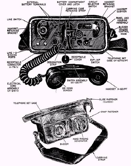
Figure 11-15.-TA-312/PT telephone set. |
 |
|
|
||