Custom Search
|
|
 
|
||
|
Few characteristics are exactly the same in two color negatives. Even when the subject matter is similar, differences can be caused by normal manufacturing variations from one emulsion to another, adverse conditions before exposure, illumination of different color quality, variance in sensitivity with changes in illumination level and exposure time (reciprocity effect), adverse storage conditions between exposure and processing (latent image loss), and nonstandard processing conditions. Most color negatives of the same subject that are exposed under similar conditions print similarly, but not identically. Differences may result from variations in lighting conditions (time of day, sky conditions, etc.), film emulsions, film processing, or other factors. These differences are normal and should be expected. The standard negative provides a good starting point for future printing requirements. For example, you made an excellent 8x10 print from the standard negative with a filter pack of 40M + 60Y and exposed the print for 10 seconds at f/5.6. The enlarger settings should remain the same as a starting point for similar negatives, providing the same type of paper is used. For a particular production negative, you may find it necessary to add a 10M filter to the pack and adjust the printing time to 11 seconds to compensate for the differences between the new negative and the standard negative. In other words, the new negative may print differently from the standard negative by a 10M filter and a 10-percent increase in printing time. The amount and types of color equipment you use depend on the volume of color production of the imaging facility where you work. A photo lab that makes occasional color prints probably uses only a standard negative and color printing viewing filters. Larger Navy imaging facilities that produce large quantities of custom color printing may use evaluation methods involving instruments, such as color analyzers, densitometers, and other electronic devices. COLOR ANALYZERS Color analyzers operate by comparing a standard negative to production negatives. For successful negative evaluation, the reference areas must have the same subject matter in all the negatives; for example, a gray card included in the picture, a flesh tone, the highlighted area of an aircraft wing, or a neutral area of a ship, all provide a suitable reference area. In portraiture, a medium-flesh tone is often selected In other fields of photography, you should either include a gray card in the scene or expose an additional negative replacing the subject with a gray card. In the latter case, the negative with the gray card is used only for evaluation purposes and is replaced by the subject negative when the print is made. When a skin tone is used instead of a gray card in portrait negatives, the color analyzer tends to reproduce all skin tones the same as the standard negative regardless of variations in skin color or lighting. Similarly, all images of a gray card tend to be printed alike regardless of the position of the card relative to the main light. Color analyzers are used to reduce the waste that is produced through the trial-and-error method of color printing. The standard negative is used as a reference when color analyzing instruments are used. There are two categories of color analyzers: off-easel and on-easel. Off-Easel Analyzers Off-easel color evaluation is performed by measuring or evaluating the color negative before it is placed in the enlarger. Commonly in Navy imaging facilities, off-easel evaluation is accomplished using a densitometer. The main advantage of using a densitometer is you can service a number of enlargers. That is especially useful when you cannot have on-easel analyzers for each color enlarger. Another advantage, off-easel evaluation can be done under normal room lighting conditions. To set up an off-easel evaluation system, you must first read the density of the reference patch from your standard negative on a transmission densitometer. You read the reference patch through a red, green, and blue filter. The densitometer provides you with direct density reading of the cyan, magenta, and yellow dyes present in the reference patch. The values that you read from the reference pack are then added to the known standard negative filter pack of the enlarger. The production
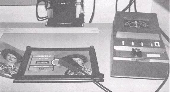
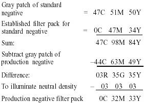
Figure 12-5. On-easel color analyzer. negative to be printed is then read on the densitometer and these densities are subtracted from the total density values of the standard negative (negative reference patch and enlarger filter pack). This method of evaluation does not indicate directly the required exposure for the production print, but the production print exposure can be estimated closely by using the standard negative exposure and compensating for any changes to the filter pack. An example on how this off-easel evaluation system operates is as follows:
A reflection densitometer also can be very useful in color print evaluation. A reflection densitometer can be used to match an earlier printed print with the color print you are currently printing. To use a reflection densitometer as an aid in color printing, you must compare or read a reference area on your test print. This is particularly useful when you are making a color print with neutral areas. As you know, black, gray, and white have approximately equal portions of red, green, and blue. By taking a reflection densitometer reading directly from one of these neutral areas (such as a gray card, the side of a ship, or part of a gray aircraft), you can determine what color and the amount of that color in excess. To change your filter pack for print corrections, you must take one half of the density value as read from the densitometer and either add or subtract that value from your filter pack; for example, you take a reflection densitometer reading from a gray patch on your color test print. Your density readings are 50R, 50G, and 70B. The densitometer indicates that your test print is high by 20B (too much yellow dye). To adjust the filter pack, you should add CC10Y to your filter pack for subtractive printing or add CC10B on an additive printer. Another off-easel color evaluation system is a color video analyzer. This system scans the color negative and is viewed directly on a color monitor. The image on the monitor can be manipulated until the proper color balance, density, and image size are achieved. The corrections are then sent through a translator device to the printer. This system has essentially been replaced with electronic darkrooms at Navy imaging facilities. On-Easel Analyzers An on-easel color analyzer (fig. 12-5) is an electronic photometer used to measure the illumination and three color primaries of light on the baseboard of the enlarger. These photometers take these measurements through tricolor filters. On-easel measurements are made conveniently by placing a small probe on the reference area of the projected image on the baseboard. This small probe is connected to a fiber-optic light tube that carries the light from the reference area to the body of the photometer. Color analyzers are programmed using standard negatives printed by the trial-and-error method of color printing. Once a good color print is made from the standard negative, the image luminance of the master negative is measured from the reference area. This reference area is read through red, green, and blue tricolor filtered sensors and finally without filters over the photocell. The analyzer scale is then zeroed for each condition. You then insert the new production negative in the enlarger and place the photocell on the same projected reference area on the easel. The aperture and dichroic filters are then changed until the meter is zeroed out once again. Most on-easel color analyzers have a number of memory channels so you can store programs for different film or paper types. The advantage of on-easel color analyzers is that, unlike off-easel evaluation, each measurement compensates for filter fading, lamp aging, and different image magnifications. Exposure and filtration are given directly. A disadvantage is that the readings must be made under the same conditions as color printing on an enlarger (complete darkness except for the illumination of the projected image of the enlarger). Both on-easel and off-easel evaluation depend strongly on accurate readings and placement and choice of a good reference area. Two methods of electronically aided color evaluation are used. They are spot or small-area measurements and large-area or integrated measurements. Small-area measurements made on the easel are the most accurate; however, a small-reference area is not always possible. When small-reference areas are not provided, large-area measurements can be taken. Large-area measurements are made usually from the whole negative area. For off-easel evaluation using a
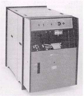
Courtesty of Kreonite Inc. Figure 12-6. Kreonite color processor, Model KCP-16. densitometer, a large photocell is used to take such readings. For on-easel analyzers, the image is integrated by placing diffusion material between the negative and the photocell. You then place the photocell and sample various areas of the projected image. These sample areas are then integrated to gray as though they were a typical subject. This type of evaluation does not compensate for images that do not contain typical color or tonal distributions; for example, when the subject of a negative is predominantly red, an integrated reading overcompensates and a cyan print results. That is called subject anomaly or subject failure. This is the method used by many automatic printers. Color prints, such as these, must be color corrected manually. |
 
|
|
|
||