Custom Search
|
|
  |
|
|
FIBER OPTIC LINKS LEARNING OBJECTIVES
FIBER OPTIC SYSTEM TOPOLOGY Most of the discussion on fiber optic data links provided earlier in this training manual refers to simple point-to-point links. A point-to-point fiber optic data link consists of an optical transmitter, optical fiber, and an optical receiver. In addition, any splices or connectors used to join individual optical fiber sections to each other and to the transmitter and the receiver are included. Figure 8-1 provides a schematic diagram of a point-to-point fiber optic data link. Figure 8-1. - A schematic diagram of a point-to-point fiber optic data link.
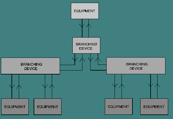
A common fiber optic application is the full duplex link. This link consists of two simple point-to-point links. The links transmit in opposite directions between the equipments. This application may be configured using only one fiber. If configured with one fiber, fiber optic splitters are used at each end to couple the transmit signal onto the fiber and receive signal to the detector. All fiber optic systems are simply sets of point-to-point fiber optic links. Different system topologies arise from the different ways that point-to-point fiber optic links can be connected between equipments. The term topology, as used here, refers to the configuration of various equipments and the fiber optic components interconnecting them. This equipment may be computers, workstations, consoles, or other equipments. Point-to-point links are connected to produce systems with linear bus, ring, star, or tree topologies. Point-to-point fiber optic links are the basic building block of all fiber optic systems. A linear bus topology consists of a single transmission line that is shared by a number of equipments (see figure 8-2). Generally the transmission line in a fiber optic linear bus consists of two optical lines, one for each direction of communication. Optical taps (optical splitters) are used by each equipment to connect to each line. For each line, the optical tap couples signals from the line to the equipment receiver and from the equipment transmitter onto the line. The connection between any two equipments is a simple point-to-point link that contains the optical tap for each equipment. Figure 8-2. - Linear bus topology. A ring topology consists of equipments attached to one another in a closed loop or ring (see figure 8-3). The connection between each equipment is a simple point-to-point link. In some systems each equipment may have an associated optical switch. In normal operation, the switch routes signals from the fiber connected to the previous equipment to the receiver. It also routes signals from the transmitter to the fiber connected to the next equipment. In bypass operation, the switch routes signals from the fiber connected to the previous equipment to the fiber connected to the next equipment. In each case, the connection between adjacent equipments on the ring is a simple point-to-point link through fiber, connectors, and switches. Figure 8-3. - Ring topology. In the star topology, each equipment is connected to a common center hub (see figure 8-4). The center hub can be a passive fiber optic star coupler or an active equipment. If the center hub is a passive star coupler, each equipment transmitter is connected to an input port of the coupler and an output port of the coupler is connected to each equipment receiver. The connection between any two equipments is a simple point-to-point link through the star coupler. If the center hub is an active equipment, the connection between any two equipments consists of two point-to-point links. Each connection consists of one link from the first equipment to the center hub and a second link from the center hub to the second equipment. Figure 8-4. - Star topology. A tree topology consists of a transmission line that branches, or splits (see figure 8-5). A tree topology may have many different branching points. At each branching point either a passive fiber optic splitter or an active branching device is used. In many cases both passive couplers and active branching devices are used within a particular system. Regardless of the branching method, each connection within the tree is a simple point-to-point link through splitters or multiple point-to-point links through active branching devices. Figure 8-5. - Tree topology.
Q.1 List four system topologies that can be constructed using point-to-point fiber
optic links. |
|
|
|
Integrated Publishing, Inc. - A (SDVOSB) Service Disabled Veteran Owned Small Business
|