Custom Search
|
|
  |
|
|
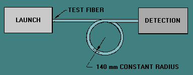
Cutoff Wavelength The wavelength at which a mode ceases to propagate is called the cutoff wavelength for that mode. However, an optical fiber is always able to propagate at least one mode, the fundamental mode. The fundamental mode can never be cut off. The cutoff wavelength of a single mode fiber is the wavelength above which the fiber propagates only the fundamental mode. Determining the cutoff wavelength of a single mode fiber involves finding the wavelength above which the power transmitted through the fiber decreased abruptly. This power decrease occurs when the second-order mode propagating in the fiber is cut off. The cutoff wavelength of single mode fibers depends on the fiber length and bend conditions. The effects of length and bending are different on different fibers depending on whether they are matched-clad or depressed-clad in design. The cutoff wavelength of matched-clad fibers is more sensitive to bends than the cuttoff wavelength of depressed-clad fibers. The cutoff wavelength of depressed-clad fibers is more sensitive to length than the cutoff wavelength of matched-clad fibers. Cutoff wavelength may be measured on uncabled or cabled single mode fibers. A slightly different procedure is used in each case, but the basic measurement process is the same. The test method for uncabled single mode fiber cutoff wavelength is EIA/TIA-455-80. The test method for cabled single mode fiber cutoff wavelength is EIA/TIA-455-170. The fiber cutoff wavelength (λcf) measured under EIA/TIA-455-80 will generally be higher than the cable cutoff wavelength (λcc) measured under EIA/TIA-455-170. The difference is due to the fiber bends introduced during the cable manufacturing process. Each test method describes the test equipment (input optics, mode filters, and cladding-mode strippers) necessary for the test. Cutoff wavelength measurements require an overfilled launch over the full range of test wavelengths. Since the procedures for measuring the cutoff wavelength of uncabled and cabled single mode fibers are essentially the same, only the test method for measuring the cutoff wavelength of uncabled fiber is discussed. Measuring the cutoff wavelength involves comparing the transmitted power from the test fiber with that of a reference fiber at different wavelengths. The reference fiber can be the same piece of single mode fiber with small bends introduced or a piece of multimode fiber. If the same fiber with small bends is used as the reference fiber, the technique is called the <emphasis type="b.GIF">bend-reference technique</emphasis>. If a piece of multimode fiber is used as the reference fiber, the technique is called the multimode-reference technique. For both techniques, the test fiber is loosely supported in a single-turn with a constant radius of 140 mm. Figure 5-5 shows this single-turn configuration. The transmitted signal power Ps (λ) is then recorded while scanning the wavelength range in increments of 10 nm or less. The launch and detection conditions are not changed while scanning over the range of wavelengths. The wavelength range scanned encompasses the expected cutoff wavelength. Figure 5-5. - Single-turn configuration for the test fiber.
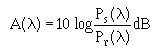
The reference power measurement is then made. For the bend-reference technique, the launch and detection conditions are not changed, but an additional bend is added to the test fiber. The test fiber is bent to a radius of 30 mm or less to suppress the second-order mode at all the scanned wavelengths. For the multimode-reference technique, the single mode fiber is replaced with a 2-m length of multimode fiber. The transmitted signal power P r(λ) is recorded while scanning the same wavelength range in the same increments of 10 nm or less. The attenuation A(λ) at each wavelength is calculated as follows:
Figure 5-6 shows an example attenuation plot generated using the bend-reference technique. The longest wavelength at which A(λ) is equal to 0.1 dB is the fiber cutoff wavelength (λcf). λ cf is marked on figure 5-6. Figure 5-6. - Fiber cutoff wavelength determined by the bend-reference technique.
Figure 5-7 shows an attenuation plot generated using the multimode-reference technique. A straight line is fitted to the long-wavelength portion of A(λ). This straight line is then displaced upward by 0.1 dB. The point at which the straight line intersects the A(λ) plot defines the fiber cutoff wavelength (λcf). Figure 5-7. - Fiber cutoff wavelength determined by the multimode-reference technique.
|
 |