Custom Search
|
|
  |
|
|
WIRING TECHNIQUES
LEARNING OBJECTIVES Upon completing this chapter, you should be able to:
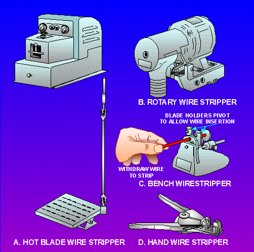
WIRING TECHNIQUES This chapter will assist you in learning the basic skills of proper wiring techniques. It explains the different ways to terminate and splice electrical conductors. It also discusses various soldering techniques that will assist you in mastering the basic soldering skills. The chapter ends with a discussion of the procedure to be followed when you lace wire bundles within electrical and electronic equipment. CONDUCTOR SPLICES AND TERMINAL CONNECTIONS Conductor splices and connections are an essential part of any electrical circuit. When conductors join each other or connect to a load, splices or terminals must be used. Therefore, it is important that they be properly made. Any electrical circuit is only as good as its weakest link. The basic requirement of any splice or connection is that it be both mechanically and electrically as sound as the conductor or device with which it is used. Quality workmanship and materials must be used to ensure lasting electrical contact, physical strength, and insulation. The most common methods of making splices and connections in electrical cables is explained in the discussion that follows. INSULATION REMOVAL The preferred method of removing insulation is with a wire-stripping tool, if available. A sharp knife may also be used. Other typical wire strippers in use in the Navy are illustrated in figure 2-1. The hot-blade, rotary, and bench wire strippers (views A, B, and C, respectively) are usually found in shops where large wire bundles are made. When using any of these automatic wire strippers, follow the manufacturer's instructions for adjusting the machine; this avoids nicking, cutting, or otherwise damaging the conductors. The hand wire strippers are common hand tools found throughout the Navy. The hand wire strippers (view D of figure 2-1) are the ones you will most likely be using. Wire strippers vary in size according to wire size and can be ordered for any size needed. Figure 2-1. - Typical wire-stripping tools.
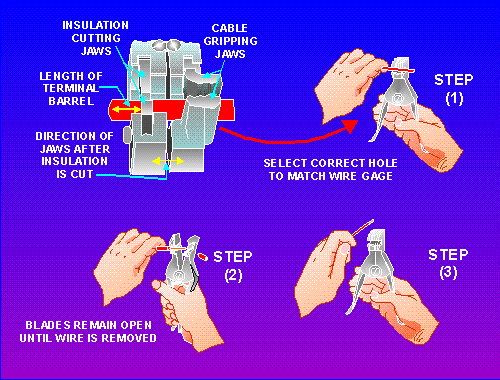
Hand Wire Stripper The procedure for stripping wire with the hand wire stripper is as follows (refer to figure 2-2): Figure 2-2. - Stripping wire with a hand stripper.
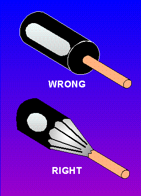
Insert the wire into the center of the correct cutting slot for the wire size to be stripped. The wire sizes are listed on the cutting jaws of the hand wire strippers beneath each slot. After inserting the wire into the proper slot, close the handles together as far as they will go. Slowly release the pressure on the handles so as not to allow the cutting blades to make contact with the stripped conductor. On some of the newer style hand wire strippers, the cutting jaws have a safety lock that helps prevent this from happening. Continue to release pressure until the gripper jaws release the stripped wire, then remove. Knife Stripping A sharp knife may be used to strip the insulation from a conductor. The procedure is much the same as for sharpening a pencil. The knife should be held at approximately a 60 angle to the conductor. Use extreme care when cutting through the insulation to avoid nicking or cutting the conductor. This procedure produces a taper on the cut insulation as shown in figure 2-3. Figure 2-3. - Knife stripping.
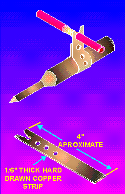
Locally Made Hot-Blade Wire Stripper If you are required to strip a large number of wires, you can use a locally made hot-blade stripper (figure 2-4) as follows: Figure 2-4. - Locally made hot-blade stripper.
|
|