Custom Search
|
|
  |
|
|
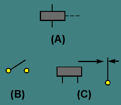
Figure 3-2. - Schematic symbol recognition.
There are thousands and thousands of switch applications found in home, industry, and the Navy. Hundreds of electrical switches work for you everyday to perform functions you take for granted. Some switches operate by the touch of a finger and many others are operated automatically. Switches are used in the home to turn off the alarm clock, to control the stove, to turn on the refrigerator light, to turn on and control radios and televisions, hair dryers, dishwashers, garbage disposals, washers and dryers, as well as to control heating and air conditioning. A typical luxury automobile with power seats and windows might have as many as 45 switches. Industry uses switches in a wide variety of ways. They are found in the business office on computers, copy machines, electric typewriters, and other equipment. A factory or shop may use thousands of switches and they are found on almost every piece of machinery. Switches are used on woodworking machinery, metal working machinery, conveyors, automation devices, elevators, hoists, and lift trucks. The Navy uses switches in a number of ways. A typical aircraft could have over 250 switches to control lights, electronic systems, and to indicate whether the landing gear is up or down. Ships, fire control systems, and missile launchers are also controlled by electrical switches. In fact, almost all electrical or electronic devices will have at least one switch. Switches are designed to work in many different environments from extreme high pressure, as in a submarine, to extreme low pressure, as in a spacecraft. Other environmental conditions to consider are high or low temperature, rapid temperature changes, humidity, liquid splashing or immersion, ice, corrosion, sand or dust, fungus, shock or vibration, and an explosive atmosphere. It would not be possible to describe all the different switches used. This chapter will describe the most common types of switches.
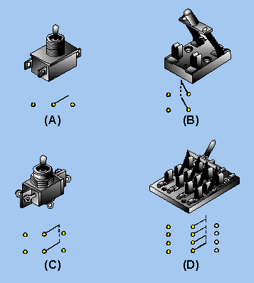
MANUAL SWITCHES A manual switch is a switch that is controlled by a person. In other words, a manual switch is a switch that you turn on or off. Examples of common manual switches are a light switch, the ignition switch on a motor vehicle, or the channel selector on a television. You may not think of the channel selector as a switch that you use to turn something on or off, but that is what it does. The channel selector is used to turn on the proper circuit and allows the television to receive the channel you have selected. AUTOMATIC SWITCH An automatic switch is a switch that is controlled by a mechanical or electrical device. You do not have to turn an automatic switch on or off. Two examples of automatic switches are a thermostat and the distributor in a motor vehicle. The thermostat will turn a furnace or air conditioner on or off by responding to the temperature in a room. The distributor electrically turns on the spark plug circuit at the proper time by responding to the mechanical rotation of a shaft. Even the switch that turns on the light in a refrigerator when the door is opened is an automatic switch. Automatic switches are not always as simple as the examples given above. Limit switches, which sense some limit such as fluid level, mechanical movement, pressure (altitude or depth under water), or an electrical quantity, are automatic switches. Computers use and control automatic switches that are sometimes quite complicated. Basically, any switch that will turn a circuit on or off without human action is an automatic switch. MULTICONTACT SWITCHES Switches are sometimes used to control more than one circuit or to select one of several possible circuits. An example of a switch controlling more than one circuit is the AM/FM selector on a radio. This switch enables you to control either the AM or FM portion of the radio with a single switch. An example of a switch that selects one of several circuits is the channel selector of a television set. These switches are called MULTICONTACT switches because they have more than one contact or MULTI(ple) CONTACTS. Number of Poles and Number of Throws Multicontact switches (other than rotary switches, which will be covered later) are usually classified by the number of POLES and number of THROWS. Poles are shown in schematics as those contacts through which current enters the switch; they are connected to the movable contacts. Each pole may be connected to another part of the circuit through the switch by "throwing" the switch (movable contacts) to another position. This action provides an individual conduction path through the switch for each pole connection. The number of THROWS indicates the number of different circuits that can be controlled by each pole. By counting the number of points where current enters the switch (from the schematic symbol or the switch itself), you can determine the number of poles. By counting the number of different points each pole can connect with, you can determine the number of throws. Figure 3-3 will help you understand this concept by showing illustrations of various multicontact switches and their schematic symbols. Figure 3-3. - Multicontact switches.
Figure 3-3(A) shows a single-pole, double-throw switch. The illustration shows three terminals (connections) on this switch. The schematic symbol for the switch is also shown. The center connection of the schematic symbol represents the point at which current enters the switch. The left and right connections represent the two different points to which this current can be switched. From the schematic symbol, it is easy to determine that this is a single-pole, double-throw switch. Now look at figure 3-3(B). The switch is shown with its schematic symbol. The schematic symbol has two points at which current can enter the switch, so this is a double-pole switch. Each of the poles is mechanically connected (still electrically separate) to one point, so this is a single-throw switch. Only one throw is required to route two separate circuit paths through the switch. Figure 3-3(C) shows a double-pole, double-throw switch and its schematic symbol. Figure 3-3(D) shows a four-pole, double-throw switch and its schematic symbol. It might help you to think of switches with more than one pole as several switches connected together mechanically. For example, the knife switch shown in figure 3-3(D) could be thought of as four single-pole, double-throw switches mechanically connected together. Q.4 What is the difference between a manual and an automatic switch? Q.5 What is one example of a manual switch? Q.6 What is one example of an automatic switch? Q.7 Why are multicontact switches used? Q.8 Label the schematic symbols shown in figure 3-4 as to number of poles and number of throws. |
 
|
| |||||||||||||||
|
|
|
|
Privacy Statement - Press Release - Copyright Information. - Contact Us - |
|
|
Integrated Publishing, Inc. - A (SDVOSB) Service Disabled Veteran Owned Small Business
|