Custom Search
|
|
  |
|
|
LEARNING OBJECTIVES Upon completion of this chapter you will be able to:
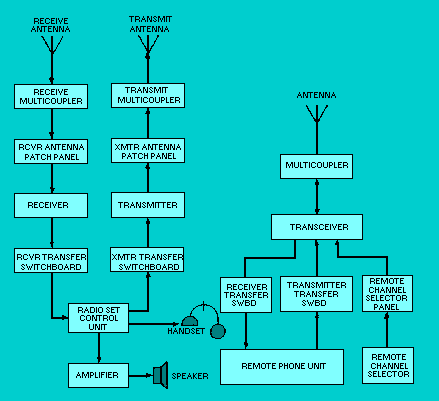
EQUIPMENT PURPOSES A communications system is a collection of equipment used together to do a specific job. You may see this equipment used to send or receive voice communications, or both, or to send, receive, or send and receive teletypewriter information. Figure 3-1 is a basic block diagram of a voice system. You can see how this equipment is interconnected to form a basic communications system.We are going to look at several of the equipment blocks in detail. Figure 3-1. - Voice system.
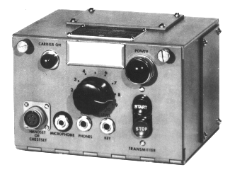
HANDSET The handset converts acoustical energy (your voice) to electrical energy for use in modulating a radio transmitter. It also converts electrical energy to acoustical energy for reproduction of a received signal. When the push-to-talk button is depressed on the handset, the dc keying circuit to the transmitter is closed, placing the transmitter on the air. Handsets are normally connected to a radio set control unit. RADIO SET CONTROL UNIT The radio set control unit shown in figure 3-2 provides a capability to remotely control some radiophone transmitter functions and the receiver output. Some of the controls are used for turning the transmitter on and off. Others are used for voice modulating the transmission (or keying when cw operation is desired). You can even control the audio output level of the receiver and silence the receiver when transmitting. Figure 3-2. - Radio set control unit.
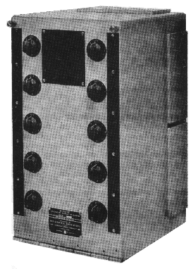
Under standard operating conditions up to four of these units can be used in parallel with a single transmitter and receiver group to provide additional operating positions. This setup is often found aboard ship where a transmitter and/or receiver is controlled and operated from several locations such as the bridge or the combat information center. TRANSFER SWITCHBOARDS A transmitter transfer switchboard provides the capability to transfer remote control station functions and signals to transmitters. Figure 3-3 is a representative transfer switchboard that provides the capability for selectively transferring any one, or all, of ten remote control station functions and signals to any one of six transmitters. The cabinet has ten rotary switches arranged in two vertical rows of five each. Each switch has eight positions. The circuitry is arranged so that you cannot parallel transmitter control circuits; that is, you cannot connect more than one transmitter to any remote control location. Figure 3-3. - Transmitter transfer switchboard.
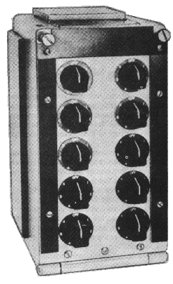
Each switch operating knob corresponds to a remote control station. Each switch position (1 through 6) corresponds to a transmitter. One switch position, X, provides for transfer of all circuits to additional transmitter transfer switchboards when more than six transmitters are installed in the system. When the rotary switch is placed in the OFF position the remote control station is removed from the system. Let's look at an example of one transfer switchboard application. When remote control station number two is to have control of transmitter number three, the switch knob designated number two is rotated until its pointer indicates position three on its dial plate. The receiver transfer switchboard permits the operator to transfer the audio output from a receiver to a remote control station audio circuit. A representative receiver transfer switchboard is shown in figure 3-4. This switchboard contains ten seven-position switches. Each switch is connected to a remote control station, and each switch position (one through five) is connected to a receiver. Figure 3-4. - Receiver transfer switchboard.
The X position on each switch allows transfer of circuits to additional switchboards just like with the transmitter transfer switchboard. Q.1 What are the basic functions of a handset? |
 
|
|
|
Integrated Publishing, Inc. - A (SDVOSB) Service Disabled Veteran Owned Small Business
|