Custom Search
|
|
  |
|
|
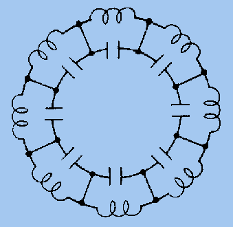
Electrical Equivalent. - Notice in figure 2-29, view (A), that the cavity consists of a cylindrical hole in the copper anode and a slot which connects the cavity to the interaction space. The equivalent electrical circuit of the hole and slot is shown in view (B). The parallel sides of the slot form the plates of a capacitor while the walls of the hole act as an inductor. The hole and slot thus form a high-Q, resonant LC circuit. As shown in figure 2-27, the anode of a magnetron has a number of these cavities. An analysis of the anodes in the hole-and-slot block reveals that the LC tanks of each cavity are in series (assuming the straps have been removed), as shown in figure 2-30. However, an analysis of the anode block after alternate segments have been strapped reveals that the cavities are connected in parallel because of the strapping. Figure 2-31 shows the equivalent circuit of a strapped anode. Figure 2-30. - Cavities connected in series.
Figure 2-31. - Cavities in parallel because of strapping.
Electric Field. - The electric field in the electron-resonance oscillator is a product of ac and dc fields. The dc field extends radially from adjacent anode segments to the cathode, as shown in figure 2-32. The ac fields, extending between adjacent segments, are shown at an instant of maximum magnitude of one alternation of the rf oscillations occurring in the cavities. Figure 2-32. - Probable electron paths in an electron-resonance magnetron oscillator.
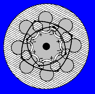
The strong dc field going from anode to cathode is created by a large, negative dc voltage pulse applied to the cathode. This strong dc field causes electrons to accelerate toward the plate after they have been emitted from the cathode. Recall that an electron moving against an E field is accelerated by the field and takes energy from the field. Also, an electron gives up energy to a field and slows down if it is moving in the same direction as the field (positive to negative). Oscillations are sustained in a magnetron because as electrons pass through the ac and dc fields, they gain energy from the dc field and give up energy to the ac field. The electrons that give up energy to the ac field are called WORKING ELECTRONS. However, not all of the electrons give up energy to the ac field. Some electrons take energy from the ac field, which is an undesirable action. In figure 2-32, consider electron Q1, which is shown entering the field around the slot entrance to cavity A. The clockwise rotation of the electron path is caused by the interaction of the magnetic field around the moving electron with the permanent magnetic field. The permanent magnetic field is assumed to be going into the paper in figure 2-32 (the action of an electron moving in an H field was explained earlier). Notice that electron Q1 is moving against the ac field around cavity A. The electron takes energy from the ac field and then accelerates, turning more sharply when its velocity increases. Thus, electron Q1 turns back toward the cathode. When it strikes the cathode, it gives up the energy it received from the ac field. This bombardment also forces more electrons to leave the cathode and accelerate toward the anode. Electron Q2 is slowed down by the field around cavity B and gives up some of its energy to the ac field. Since electron Q2 loses velocity, the deflective force exerted by the H field is reduced. The electron path then deviates to the left in the direction of the anode, rather than returning to the cathode as did electron Q1. The cathode to anode potential and the magnetic field strength determine the amount of time for electron Q2 to travel from a position in front of cavity B to a position in front of cavity C. Cavity C is equal to approximately 1/2 cycle of the rf oscillations of the cavities. When electron Q2 reaches a position in front of cavity C, the ac field of cavity C is reversed from that shown. Therefore, electron Q2 gives up energy to the ac field of cavity C and slows down even more. Electron Q2 actually gives up energy to each cavity as it passes and eventually reaches the anode when its energy is expended. Thus, electron Q2 has helped sustain oscillations because it has taken energy from the dc field and given it to the ac field. Electron Q1, which took energy from the ac field around cavity A, did little harm because it immediately returned to the cathode. The cumulative action of many electrons returning to the cathode while others are moving toward the anode forms a pattern resembling the moving spokes of a wheel known as a SPACE-CHARGE WHEEL, as indicated in figure 2-33. Electrons in the spokes of the wheel are the working electrons. The space-charge wheel rotates about the cathode at an angular velocity of 2 poles (anode segments) per cycle of the ac field. This phase relationship enables the concentration of electrons to continuously deliver energy to sustain the rf oscillations. Electrons emitted from the area of the cathode between the spokes are quickly returned to the cathode. In figure 2-33 the alternate segments between cavities are assumed to be at the same potential at the same instant. An ac field is assumed to exist across each individual cavity. This mode of operation is called the PI MODE, since adjacent segments of the anode have a phase difference of 180 degrees, or one-pi radian. Several other modes of oscillation are possible, but a magnetron operating in the pi mode has greater power and output and is the most commonly used. Figure 2-33. - Rotating space-charge wheel in an eight-cavity magnetron.
An even number of cavities, usually six or eight, are used and alternate segments are strapped to ensure that they have identical polarities. The frequency of the pi mode is separated from the frequency of the other modes by strapping. For the pi mode, all parts of each strapping ring are at the same potential; but the two rings have alternately opposing potentials, as shown in figure 2-34. Stray capacitance between the rings adds capacitive loading to the resonant mode. For other modes, however, a phase difference exists between the successive segments connected to a given strapping ring which causes current to flow in the straps. Figure 2-34. - Alternate segments connected by strapping rings.
The straps contain inductance, and an inductive shunt is placed in parallel with the equivalent circuit. This lowers the inductance and increases the frequency at modes other than the pi mode. Q.38 What is the primary difference in construction between the basic magnetron and the
negative-resistance magnetron? |
 
|