| Tweet |

Custom Search
|
|
 
|
||
|
CHAPTER 6 GEARS CHAPTER LEARNING OBJECTIVES Upon completion of this chapter, you should be able to do the following:
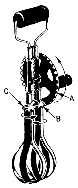
Did you ever take a clock apart to see what made it tick? Of course you came out with some parts left over when you got it back together again. And they probably included a few gear wheels. We use gears in many machines. Frequently the gears are hidden from view in a protective case filled with grease or oil, and you may not see them. An eggbeater gives you a simple demonstration of the three jobs that gears do. They can change the direction of motion, increase or decrease the speed of the applied motion, and magnify or reduce the force that you apply. Gears also give you a positive drive. There can be, and usually is, creep or slip in a belt drive. However, gear teeth are always in mesh, so there can be no creep and slip. Follow the directional changes in figure 6-1. The crank handle turns in the direction shown by the arrowclockwisewhen viewed from the right. The 32 teeth on the large vertical wheel (A) mesh with the 8 teeth on the right-hand horizontal wheel (B), which rotates as shown by the arrow. Notice that as B turns in a clockwise direction, its teeth mesh with those of wheel C and cause wheel C to revolve in the opposite direction. The rotation of the crank handle has been transmitted by gears to the beater blades, which also rotate. Now figure out how the gears change the speed of motion. There are 32 teeth on gear A and 8 teeth on gear B. However, the gears mesh, so that one complete revolution of A results in four complete revolutions of gear B. And since gears B and C have the same number of teeth, one revolution of B results in one revolution of C. Thus, the blades revolve four times as fast as the crank handle. In chapter 1 you learned that third-class levers increase speed at the expense of force. The same happens with the eggbeater. The magnitude of force changes. The force required to turn the handle is greater than the force applied to the frosting by the blades. This results in a mechanical advantage of less than one. TYPES OF GEARS When two shafts are not lying in the same straight line, but are parallel, you can transmit motion from
Figurc 6-1.A simple gear arrangement.
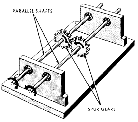
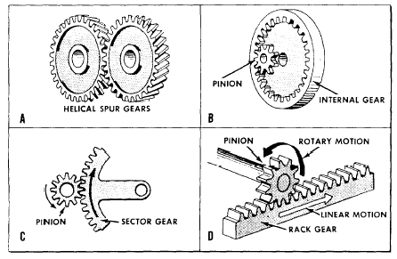
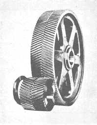
Figure 6-2.4-Spur gears coupling two parallel shafts. one to the other by spur gears. This setup is shown in figure 6-2. Spur gears are wheels with mating teeth cut in their surfaces so that one can turn the other without slippage. When the mating teeth are cut so that they are parallel to the axis of rotation, as shown in figure 6-2, the gears are called straight spur gears. When two gears of unequal size are meshed together, the smaller of the two is usually called a pinion. By unequal size, we mean an unequal number of teeth causing one gear to be a larger diameter than the other. The teeth, themselves, must be of the same size to mesh properly. The most commonly used gears are the straight spur gears. Often youll run across another type of spur gear called the helical spur gear. In helical gears the teeth are cut slantwise across the working face of the gear. One end of the tooth, therefore, lies ahead of the other. Thus, each tooth has a leading end and a trailing end. Figure 6-3, view A, shows you the construction of these gears. In the straight spur gears, the whole width of the teeth comes in contact at the same time. However, with helical (spiral) gears, contact between two teeth starts first at the leading ends and moves progressively across the gear faces until the trailing ends are in contact. This kind of meshing action keeps the gears in constant contact with one another. Therefore, less lost motion and smoother, quieter action is possible. One disadvantage of this helical spur gear is the tendency of each gear to thrust or push axially on its shaft. It is necessary to put a special thrust bearing at the end of the shaft to counteract this thrust. You do not need thrust bearings if you use herringbone gears like those shown in figure 6-4. Since the teeth on each half of the gear are cut in opposite directions, each half of the gear develops a thrust that counterbalances the other half. Youll find herringbone gears used mostly on heavy machinery.
Figure 6-3.-Gear types.
Figure 6-4.Herringbone gear. Figure 6-3, views B, C, and D, also shows you three other gear arrangements in common use. The internal gear in figure 6-3, view B, has teeth on the inside of a ring, pointing inward toward the axis of rotation. An internal gear is meshed with an external gear, or pinion, whose center is offset from the center of the internal gear. Either the internal or pinion gear can be the driver gear, and the gear ratio is calculated the same as for other gearsby counting teeth. You only need a portion of a gear where the motion of the pinion is limited. You use the sector gear shown in figure 6-3, view C, to save space and material. The rack and pinion in figure 6-3, view D, are both spur gears. The rack is a piece cut from a gear with an extremely large radius. The rack-and-pinion arrangement is useful in changing rotary motion into linear motion.
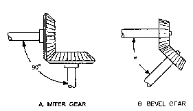
Figure 6-5.-Bevel gears. |
||
|
||