Custom Search
|
|
 
|
||
|
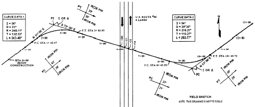
SURVEY When it is decided that a road is needed through a particular area, the first and logical step is to determine a route for it to follow. This mute may be chosen by the use of maps, aerial photographs, aerial reconnaissance, ground vehicle reconnaissance, walk-through reconnaissance, or by any combination of these. Once the route is chosen, a surveying crew makes the preliminary survey. This survey consists of a series of traverse lines connecting a series of traverse stations. A survey party will stake in each of the traverse stations and determine the bearing and distance of the connecting traverse lines. From this information, an Engineering Aid will draw the points of intersection (PI) and the connecting lines. Then an engineer will compute the horizontal curves at each point of intersection, and an Engineering Aid will draw the curves and mark the stationing. This drawing is the proposed center line.
Figure 3-3.The road plan. The drawing of the proposed center line is then given to a final location party, which stakes in the center line and curves. With the approval of the engineer, the party chief may make changes in alignment of the center line, but the changes must be recorded. Once the final location is determined, all information and changes pertinent to the location are used to prepare a second and final drawing, showing the final center-line location, construction limits, all curves and curve data, station marks, control points, natural and man-made terrain features, trees, buildings, and anything else that is helpful in construction. This drawing, known as a road plan (fig. 3-3), is a "birds-eye view" of the road and shows what you should see from a position directly above. The road plan is drawn on the upper portion of plan-and-profile paper, using any scale desired. The bottom portion of the plan-and-profile paper, which, as you know, is composed of grid lines, is reserved for drawing the road profile.ROAD PLAN The road plan, or plan view, shows the actual location and length of the road measured along the center line. The length is determined by station points, which are set at full station (full stations are 100 feet or 100 meters apart), half station, or one-tenth station intervals. Odd-station points are set at major breaks in the terrain. Referring to figure 3-3, you see the manner in which the beginning station (0 + 00) is shown, and you also see the manner in which the full stations and the partial stations are shown. Recalling your study of the EA3 TRAMAN, you know, then, that the distance from the beginning station to the last full station shown (13 + 00) is 1,300 feet.All man-made and natural objects, such as trees, buildings, fences, wells, and so on, are also plotted on the plan if they are in the right-of-way or construction limits. (Right-of-way is the land acquired for the road construction.) Identification and location of these objects are taken from the surveyors notebook Their location is determined by a station number and distance from the center line. All measurements and distances are made perpendicular to the center line of the particular station unless otherwise noted. |
 
|
|
|
||