Custom Search
|
|
 
|
||
|
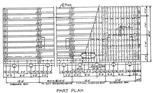
WHARFAGE STRUCTURES Wharfage structures are designed to allow ships to lie alongside for loading and discharge. Figure 1-21 shows various plan views of wharfage structures. Any of these may be constructed of fill material, supported by bulkheads. However, a pier or marginal wharf usually consists of a timber, steel, or concrete superstructure, supported on a substructure of timber-, steel-, or concrete-pile bents.Working drawings for advanced-base piers are contained in Facilities Planning Guide, Volume 1, NAVFAC P-437. Figures 1-22, 1-23, and 1-24 are portions of the advanced-base drawing for a 40-foot timber pier.Each part of a pier lying between adjacent pile bents is called a bay, and the length of a single bay is equal to the on-center spacing of the bents. In the general plan shown in figure 1-22, you can see that the 40-foot pier consists of one 13-foot outboard bay, one 13-foot inboard bay, and as many 12-foot interior bays as needed to meet the length requirements for the pier.The cross section shown in figure 1-24 shows that each bent consists of six bearing piles. The bearing piles are braced transversely by diagonal braces. Additional transverse bracing for each bent is provided by a pair of batter piles. The batter angle is specified as 5 in 12. One pile of each pair is driven on either side of the bent, as shown in the general plan. The butts of the batter piles are joined to 12-inch by 12-inch by 14-foot longitudinal batter-pile caps, each of which is bolted to the undersides of two adjacent bearing-pile caps in the positions shown in the part plan. The batter-pile caps are placed 3 feet inboard of the center lines of the outside bearing piles in the bent. They are backed by 6- by 14-inch batter-pile cap blocks, each of which is bolted to a bearing-pile cap. Longitudinal bracing between bents consists of 14-foot lengths of 3 by 10 planks, bolted to the bearing piles.
Figure 1-22.General
plan of an advanced-base 40-foot timber pier.
Figure 1-23.Part plan of an advanced-base timber pier. Figure 1-24.Cross section of an advanced-base timber pier.
Figure 1-25.Dolphins.
The superstructure (fig. 1-24) consists of a single layer of 4 by 12 planks
laid on 19 inside stringers measuring 6 inches by 14 inches by 14 feet. The
inside stringers are fastened to the pile caps with driftbolts. The outside
stringers are fastened to the pile caps with bolts. The deck planks are fastened
to the stringers with 3/8- by 8-inch spikes. After the deck is laid, 12-foot
lengths of 8 by 10 are laid over the outside stringers to form the curbing. The
lengths of curbing are distributed as shown The pier is equipped with a fender system for protection against shock, caused by contact with vessels coming or lying alongside. Fender piles, spaced as shown in the part plan, are driven along both sides of the pier and bolted to the outside stringers. The heads of these bolts are countersunk below the surfaces of the piles. An 8-by-10 fender wale is bolted to the backs of the fender piles. Lengths of 8-by-10 fender-pile chocks are cut to fit between the piles and bolted to the outside stringers and the fender wales. The spacing for these bolts is shown in the part plan. As shown in the general plan, the fender system also includes two 14-pile dolphins, located 15 feet beyond the end of the pier. A dolphin is an isolated cluster of piles, constructed as shown in figure 1-25. A similar cluster attached to a pier is called a pile cluster. |
 
|
|
|
||