Custom Search
|
|
 
|
||
|
ANTENNA DISTRIBUTION SYSTEMS In figure 2-36, we see a distribution system with one antenna that can be connected (patched) to one of several receivers or transmitters by way of a multicoupler. In this system, you can patch the antenna to only one receiver or transmitter at a time. However, some distribution systems are more complex, such as the one shown in figure 2-37. In this system, you can patch four antennas to four receivers, or you can patch one antenna to more than one receiver via the multicoupler. In either system, we need a way to connect the antenna to the receiver or transmitter that we want to use.
Figure 2-37.-Complex distribution system.
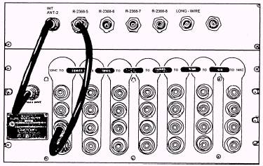
Figure 2-38.-AN/SRA-12 antenna filter patch panel with receiver antenna patch panel.
Figure 2-38 shows a receiver antenna filter patch panel, AN/SRA-12, with a receiver patch panel. The AN/SRA-12 provides seven radio-frequency channels in the 14-kHz to 32-MHz range. Any or all of these channels can be used independently of any other channel, or they can operate simultaneously. On the receiver patch panel, a receiver is hardwired to each jack. With the use of patchcords, you can connect a receiver, tuned to a particular frequency, to the antenna by connecting the receiver to the proper jack on the AN/SRA-12. Figure 2-38 shows how the filter assembly is used in combination with other units to pass an RF signal from an antenna to one or more receivers. NOTE When patching, YOU MUST ALWAYS INSERT THE END OF THE ANTENNA PATCH CORD TO THE RECEIVER JACK FIRST. THEN, YOU INSERT THE OTHER END OF THE PATCH CORD INTO THE LOWEST USABLE AN/SRA-12 JACK. TO UNPATCH, ALWAYS REMOVE THE PATCH CORD FROM THE RECEIVER JACK, THEN THE OTHER END FROM THE FREQUENCY FILTER JACK. An easy way to remember this is always work the patching from the top down. Transmitting antenna distribution systems perform the same functions as receiving distribution systems. Figure 2-39 shows a transmitter patch panel. These
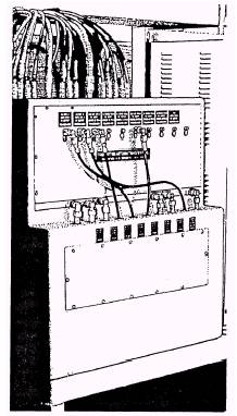
Figure 2-39.-Transmitter antenna patch panel. transmitter patch panels are interlocked with the transmitter so that no open jack connection can be energized and no energized patch cord can be removed. This provides safety for both personnel and equipment. ANTENNA POSITIONING Raise and lower antennas - raising and lowering physically of antennas is associated with flight, refueling or PMS operations. Extreme care should be taken that all moving parts are in correct operating conditions and the Officer of the Deck or Communications Watch Officers know prior to the physical movement of the antennas. |
 
|
|
|
||