Custom Search
|
|
 
|
||
|
QUARTER-WAVE ANTENNA A quarter-wave antenna is a grounded antenna that is one-fourth wavelength of the transmitted or received frequency. You will hear the quarter-wave antenna referred to as a "Marconi antenna." The quarter-wave antenna is also omnidirectional. As we mentioned earlier, a half-wave antenna is the shortest practical length that can be effectively used to radiate radio signals into free space. The natural question, then is, "How do we use a quarter-wavelength antenna if a half-wavelength is the shortest length that can be used?" The answer is simple.
Figure 2-20.-Direct and image signal of a quarter-wave antenna.
Figure 2-21.-Current distribution in a real antenna and its image. Two components make up the total radiation from an antenna. One component is that part of the radiated signal which leaves the antenna directly. The other is a ground reflection that appears to come from an underground image of the real antenna (figure 2-20). This image is sometimes called the mirror image and is considered to be as far below the ground as the real antenna is above it.
Figure 2-21 shows basic current distribution in a real and image antenna. There are certain directions in which the direct wave from the real antenna and the reflected wave from the image are exactly equal in amplitude but opposite in phase. Conversely, there are other directions in which the direct and reflected waves are equal in amplitude and in phase. Therefore, depending on the direction and location of the point at which the field strength is measured, the actual field strength may be (1) twice the field strength from the real antenna alone, (2) zero field strength, or (3) some intermediate value between maximum and minimum. It is this "real" and "image" radiated field that forms the basis for using quarter-wavelength antennas. This reflected-energy principle is very useful in the lower frequency ranges, although ground reflections occur in the high-frequency range as well. The antenna does not always need to be placed at the Earth's surface to produce an image. Another method of achieving reflected images is through the use of ground planes. This means that a large reflecting metallic surface is used as a substitute for the ground or Earth. This method is frequently used in the VHF/UHF
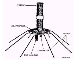
Figure 2-22.-AS-390/SRC UHF antenna with counterpoise, or ground plane. frequency ranges. Figure 2-22 shows a commonly used UHF antenna (AS-390/SRC), which uses this principle. The ground plane is sometimes referred to as a "counterpoise," as shown in the figure. Together, the counterpoise and the radials form the reflecting surface, which provides the reflected image. |
||
|
||