Custom Search
|
|
 
|
||
|
Pressure Regulators The control and unloading valves shown in figure 4-18 are used to regulate the operating pressure in an accumulator power drive system. The operating range of the fluid pressure for the functional description that follows is assumed to be 950 psi to 1,050 psi. The control valve and its piston maintain the operating range of the fluid pressure of the system by controlling the position of the unloading valve. The unloading valve (also called a bypass valve) is a three-way, plunger type of directional valve. Its function is to port the pump output to the accumulator during a charge cycle or to the tank (back to the reservoir) during an unloading cycle. During an accumulator charging cycle (fig. 4-18, part A), the spring holds the control valve in the DOWN position. A drilled hole through the lower land of the control valve ports system pressure (PA) from the accumulator to the chamber between the control valve and its piston. The' piston has PA applied to both ends and, therefore, does not affect operation of the control valve during this portion of the cycle. However, PA is only applied to the lower end of the control valve. The position of the control valve is determined by the amount of pressure in the accumulator system. As the pressure increases, the valve moves upward against spring pressure. During the charging cycle, PA is also ported from the upper chamber of the control valve to the spring-loaded (large area) side of the unloading valve. Pump output is also applied to the lower area around the seat (small area) of the unloading valve. The combination of spring pressure and PA on the large area keeps the unloading valve on its seat. In this position, fluid discharged by the pump is ported to the accumulator. As fluid pressure in the accumulator increases, it forces the control valve upward against its spring pressure. When the pressure reaches 1,050 psi, the lower land of the control valve blocks PA and the upper land uncovers the tank line (part B). This vents the
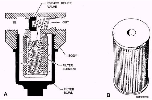
Figure 4-17.-A. A full-flow filtering device; B. A micronic filter element.
Figure 4-18.--Control and unloading valves. pressure from the chamber between the control valve and its piston and from the large area side of the unloading valve. With no pressure in the chamber between the control valve and its piston, the piston moves upward into contact with the valve. Because the piston is larger in diameter (more working area for the fluid pressure) than the control valve, the control valve moves further up against spring pressure. When the pressure is vented from the large area side of the unloading valve, the pressure in the pump output line, acting on the area around the seat of the unloading valve, overcomes spring pressure and shifts the valve upward. This causes pump output to be discharged to tank. During the unload cycle, PA, acting on the bottom of the control valve piston, holds the control valve in the UP position against spring pressure. As the pressure in the accumulator system decreases, spring pressure overcomes fluid pressure, moving both the control valve and its piston downward. When system pressure decreases to 950 psi, the upper land of the control valve covers the tank line and the lower land opens the PA line. PA enters the chamber between the control valve and its piston. PA is also ported to the large area side of the unloading valve, forcing it on its seat and beginning another charging cycle. |
||
|
||