Custom Search
|
|
 
|
||
|
GEAR TRAINS Gears are used in almost all types of ordnance equipment. They are used to change direction of motion, to increase or decrease the speed of applied motion, and to magnify or reduce applied force. Gears also give you positive drive. There can be, and usually is, some slippage in a belt drive. Gear teeth, however, are always in mesh so there can be no slippage. This is true as long as the teeth are in good shape and not worn. Gears in ordnance equipment are normally not seen. They are usually encased in a gearbox, filled with
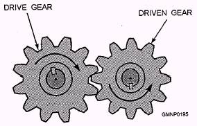
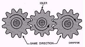
Figure 4-3.-Gears used to reverse the direction of rotation. a gear lubricant. You can be sure gears and gear trains are at the heart of almost every type of machine. Changing Direction of Motion Figure 4-3 represents the fundamental concept of reversing direction of rotation with gears. We have two gears in this simple gear train: the drive gear and the driven gear. The drive gear is rotating in a clockwise direction. This turns the driven gear in a counterclockwise direction, reversing the direction of rotation. This quality is inherent in all gear trains; one gear turning another will always reverse the direction of motion. This is not always the desired result. To overcome this, you can insert an idler gear between the drive gear and the driven gear, as shown in figure 4-4. The idler reverses the direction of motion coming from the drive gear. This allows the driven gear to be turned in the same direction as the drive gear.
Figure 4-4.-The function of an idler gear.
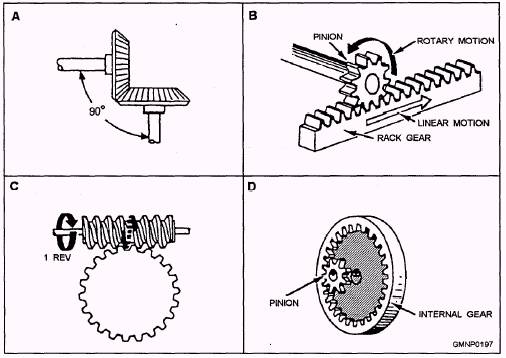
Figure 4-5.-Gear configurations. Another form of direction change performed by gear trains is a change in angular direction. Figure 4-5 shows some of the different gear configurations used to change angular direction of motion. The first, and most common, is the bevel gear (fig. 4-5, view A). Bevel gears can be used to turn just about any angle. There are several different forms of bevel gears. The difference is in how the teeth are cut. The rack-and-pinion gear (view B) is used in cases where linear motion is desired. Worm gears (view C) area special type of gear train. They have a unique property that makes them very useful for train and elevation drive trains and ammunition hoists. A worm gear can transmit motion in only one direction through the worm. In application, this means that should you lose power halfway through a hoist cycle, the hoist and ammunition will not "free-fall" back to the bottom of the hoist. View D shows a pinion and an internal gear. Either can serve as the drive gear. This configuration is used in most missile launcher and gun mount train drives. The internal gear is mounted stationary in the stand, while the pinion is part of the mount or launcher. The train drive motor transmits motion through a worm gear to the pinion, which walks around the inside of the internal gear, moving the mount or launcher with it. |
 |
|
|
||