Custom Search
|
|
 
|
||
|
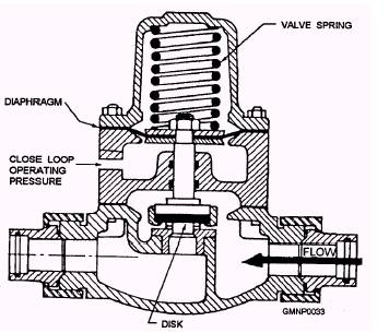
Spring-Loaded Lift Check Valves This valve (fig. 2-17) is a spring-loaded, diaphragm-operated lift check valve that closes tightly against reverse flow and opens wide to permit flow in the normal direction. Spring-loaded lift check valves permit the control system to be operated from more than one control station by preventing backflow through the other stations. Hydraulically Operated Check Valves The hydraulically operated check valve (fig. 2-18) is a normally closed, diaphragm-operated, globe-type check valve that is opened by operating pressure in the close loop acting against the underside of the diaphragm. This valve permits the operating pressure to be vented from the diaphragm chamber of the magazine sprinkler valve, thereby permitting that valve to close rapidly and completely. This valve is normally installed in conjunction with the diaphragm-operated magazine sprinkler valve.
Figure 2-18.-Hydraulically operated check valve. Power-Operated Check Valves The power-operated check valve (fig. 2-19) is a normally closed, piston-operated, poppet-type valve that is opened by operating pressure from the close loop of the operating pressure circuit acting against the piston. When the valve opens, the operating pressure is released from the piston of the magazine sprinkler valve, thereby permitting the valve to close completely. This valve is normally installed in conjunction with the piston-operated magazine sprinkler valve. Orifices There are two 0.098-inch orifices installed in the control system piping. The primary purpose of the orifices is to prevent a buildup of pressure in the control system piping as a result of leakage past a control system component. Additionally, the orifices serve to vent the
Figure 2-19.-Power-operated check valve. operating pressure from the control system piping when the manual control valve is returned to the NEUTRAL position. Orifice No. 1 is installed in the open loop upstream from the hydraulically operated check valve. Orifice No. 2 is installed in the close loop adjacent to the operating pressure connection of the hydraulically operated check valve. When the control system is actuated, there will be a steady flow of water from orifice/drain line No. 1 and no flow from orifice/drain line No. 2. When the control system is secured, there will be a steady flow of water from orifice/drain line No. 2 and a diminishing flow from orifice/drain line No. 1. When the manual control valve is returned to the NEUTRAL position, the operating pressure is vented from the close loop via orifice/drain line No. 2, thereby permitting the hydraulically operated check valve to close. The orifices and valves of the hydraulic control system described in this section are illustrated in figure 2-20 by symbols. Pay particular note to the legend list for the symbols. In addition to the orifices and valves, this figure also identifies the open and close loops of the operating pressure circuit. |
||
|
||