Custom Search
|
|
 
|
||
|
CONTROL LEARNING OBJECTIVE: Recall the aerodynamic forces and basic motions that impact on the design and performance of a missile. Before we examine the control system of a missile, it is important to understand a little about aerodynamics. Aerodynamics is the science that deals with the motion
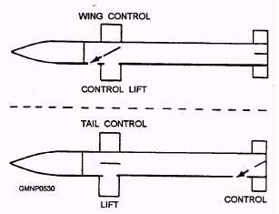
Figure 9-3.-Missile airframe design with respect to control surface location.
Figure 9-4.-Missile configurations. of air and other gases. It also considers the forces acting on bodies moving through these gases. The principles of aerodynamics that apply to the operation of most aircraft also apply to high-speed missiles. AERODYNAMIC FORCES The principal forces acting on a missile in level flight are thrust, drag, weight, and lift. Like any force, each of these is a vector quantity that has magnitude and direction. These forces are shown in figure 9-5. Thrust is directed along the longitudinal axis of the missile is the force that propels the missile forward at speeds sufficient to sustain flight. Drag is the resistance offered by the air to the passage of the missile through it. This force is directed rearward. Weight is comparable to the force of gravity acting on missile. This force is directed downward to the center of the Earth. Lift is an upward force that supports the missile in flight. Lift opposes the force of gravity and is directed perpendicular to the direction of drag. Lift is the force that concerns us the most.
Figure 9-5.-Forces acting on a moving missile. Lift is produced by means of pressure differences. The primary requirement for lift is that the air pressure on the upper surface of an airfoil (wing or fin) be less than the pressure on the underside. The amount of lifting force produced is dependent, to a large extent, on the shape of the airfoil. Additional factors also determine the amount of lift. The airfoil area and the angle at which its surface is inclined to an airstream affect lift. The air speed and air density passing around the airfoil are two more factors. The airfoil that provides the greatest lift with the least drag in subsonic flight has a curved (or camber) shape (fig. 9-6). Some standard airfoil terms are also included in the drawing on figure 9-6. The foremost edge of the airfoil is the leading edge. The rear edge is the trailing edge. A straight line between the leading and trailing edges is the chord. The large arrow (in view B) indicates relative wind or the direction of airflow in respect to the moving airfoil. The angle of attack is the angle between the chord and the direction of relative wind. As relative wind strikes the airfoils tilted surface, air flows around its upper and lower surfaces. Different amounts of lifting force are exerted on various points of the airfoil. The sum of all these forces is equal to a single force acting on a single point and in a particular direction. This point is the center of pressure. From here, lift is in a direction perpendicular to relative wind. The dynamic or impact force of the relative wind against the airfoils lower surface contributes to lift. However, the major portion of the lifting force is obtained from the pressure differential above and below the airfoil. The angle of attack causes the air flowing over the airfoils upper surface to travel a greater distance. The farther the air has to travel, the faster it moves. Faster speed creates a lower pressure. Therefore, since the air pressure above the airfoil is less than that below it, the result is lift. The magnitude of the lifting force is proportional to the pressure difference.
Figure 9-6.-Wing cross section. |
 |
|
|
||