Custom Search
|
|
 
|
||
|
Strikedown Offload and Intertransfer A strikedown offload is a reverse sequence of onload operations. Intertransfer operations change the distribution pattern of the magazine load. Intertransfer uses a combination of onload and offload procedures performed solely below deck. The marine hatch remains closed, and the MCC operator controls all equipment functions. The operation may be accomplished in step or automatic control.
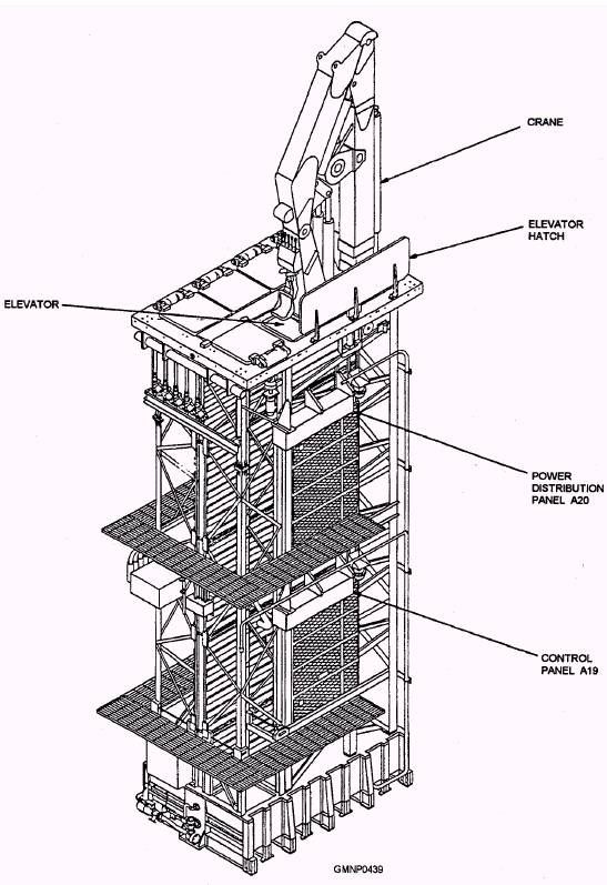
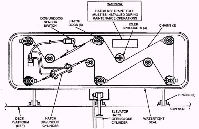
Figure 8-13.-5-cell strikedown module Mk 3 Mod 0. MK 41 VERTICAL LAUNCHING SYSTEM The Mk 41 vertical launching system (VLS) strikedown equipment is housed in the 5-cell strikedown module Mk 3 Mod 0 (fig. 8-13). This strikedown equipment occupies cells 6, 7, and 8-the same cell space used in 8-cell modules Mk 1 Mod 0 and Mk 2 Mod 0 for missiles. The VLS strikedown equipment gives the VLS crew self-contained equipment that can be used to onload and offload missile canisters Mk 13 and Mk 15 and training canister Mk 19 into and out of the module cells. The strikedown equipment can also be used to remove any empty canisters and movother strikedown equipment as necessary. Strikedown Equipment The five-cell strikedown module consists of three subassemblies: the elevator hatch, elevator, and crane assemblies. When not in use, the hatch is closed and the elevator and crane are stored below deck until onload or offload operations. ELEVATOR HATCH ASSEMBLY.- The elevator hatch assembly (fig. 8-14) is hinged to the deck platform. This assembly provides weather and ballistic protection for the strikedown crane, elevator, and launcher interior. The hatch is driven open or closed by the elevator hatch cylinder. When closed, the hatch is secured by six hatch dogs. The hatch dogs apply pressure to a watertight seal. The dogs are linked together and actuated by two chains, which are connected to, and operated by, the hatch dog/undog cylinder. Two directional control valves, located below
Figure 8-14.-Elevator hatch in OPEN position.
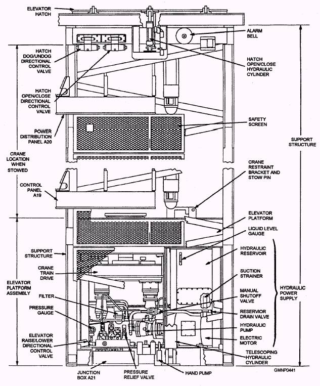
Figure 8-15.-Elevator assembly Mk 2 Mod 0. the hatch on the walkway side (fig. 8-15), direct the flow of hydraulic fluid to the hatch dog/undog cylinder and the open/close hatch cylinder. The valves can be actuated manually in an emergency. The hatch operation is controlled by toggle switches located on the control panel A19. |
 |
|
|
||