Custom Search
|
|
 
|
||
|
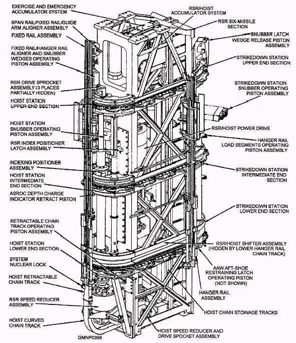
MOD AND SERIAL NUMBER DIFFERENCES The Mk 26 GMLS is currently divided into six different Mods that differ mainly in missile-stowage capacities and "value engineering design changes." Refer to figure 7-17. The magazine of the Mod 0, called the basic system, contains two RSRs that can stow 12 missiles each. By adding one lo-missile module to each RSR, the Mod 0 becomes a Mod 1; likewise, by adding two 10-missile modules to each RSR, the Mod 0 becomes a Mod 2. The Mod 0, then, can stow 24 missiles; the Mod 1, 44 missiles; and the Mod 2, 64 missiles. The first eight systems manufactured were assigned serial numbers 1 through 8 and are currently the Mods 0, 1, and 2 systems. They are primarily installed on the CGN-38 Virginia class. Mk 26 systems with serial numbers 9 through 18 have incorporated valuable engineering design changes into various components of the launching, loading, strikedown/intertransfer, and control system. These design changes alter the physical characteristics of components and systems without affecting their functional characteristics. Generally, these minor design changes were made to reduce system cost and weight. They also improved system reliability, maintainability, and availability (RMA). These systems were originally built as Mod 0s and Mod 1s but, because of the number of changes made, are now designated Mod 3s (old Mod 0s) and Mod 4s (old Mod 1s). They are primarily installed on the DDG-993 Kidd class. The Mk 26 Mod 5s are installed on the CG-47 Ticonderoga-class ships with the AEGIS weapons system. Additional design changes have been made to interface with the AEGIS equipments. The magazine capacity is the same as Mod 1 and 4 systems. The magazine size of the different Mods also affects some auxiliary equipment. The amount of piping needed for the sprinkling and water injection systems grows with the magazine stowage capacity. The extra piping also needs more pressurized seawater. Ship air-conditioning demands differ among the various Mods. The launcher is the same for all six Mods. Except for internal logic circuitry and some panel displays, the ICS for each Mod is the same. The strikedown/ intertransfer mechanism is unchanged. However, additional RSR modules do move the mechanism farther from the launcher. For normal tactical operation, four persons are required to run the system. The main control console (MCC) operator activates, readies, and monitors system functioning. A launching system captain is in charge of the ICS and supervises total system operation. Two other personnel are assigned as fin assemblers/folders and remain at-the-ready in the ICS. They also help observe magazine equipment operation through the two observation windows and visually verify that correct missiles are at the hoist positions. The text will now provide a general physical description of the major component areas of the Mk 26 GMLS. We will use the Mod 0 configuration (the basic system) as our model, and only the A-side equipments will be covered. Be particularly alert to the terminology associated with the Mk 26 GMLS. MAGAZINE The magazine is a below deck, weathertight compartment for handling and stowing the missiles in an environmentally controlled condition. Its components perform all operations involved with loading, unloading, strikedown, and intertransfer. Ready Service Ring (RSR) A complete 12-missile RSR (fig. 7-19) is made by joining three basic support structures: a hoist end, a six-missile section, and a strikedown end (assembled in that order). The two end sections are structurally similar and provide space to mount three hanger rail assemblies apiece. The six-missile section is inserted between the end sections and is fastened to the magazine deck. It also supports the launcher platform above. It has space for three hanger rail assemblies along each side. To increase magazine capacity, either one (Mods 1, 4, and 5) or two (Mod 2) 10-missile sections are added to a basic RSR. (See fig. 7-17.) Physically placed between a six-missile section and the strikedown end, a lo-missile section provides space for five hanger rail assemblies along each side.
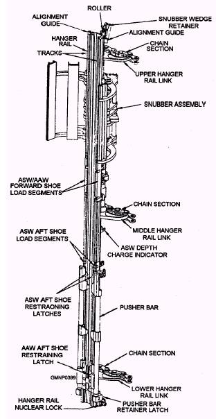
Figure 7-19.-RSR components, general arrangement. Each basic section has three hanger rail chain tracks (upper, intermediate, and lower) that guide the hanger rail chains. A roller track, mounted just above the lower chain track, guides the hanger rail rollers. The hoist end also has six proximity switches gang-mounted near its bottom. As the hanger rails move past these switches, rail-mounted actuators activate them in various combinations. This action identifies to the control system individual hanger rails according to the number assigned them. Hanger Rail Assemblies A hanger rail assembly (fig. 7-20) is made up of a 13-foot structural rail column. The individual
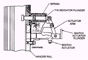
Figure 7-20.-Hanger rail assembly. components of the hanger rail support and hold a missile on the RSR. Mounted on the back of each column are three chain sections with rail links. When joined to other hanger rails, three continuous chains are formed around the RSR. They secure the rails to the RSR and provide a means for indexing. A hanger rail roller supports the assembly vertically in the RSR roller track. Rail tracks on the front of the column engage and guide the pusher bar, missile shoes, and hoist chain. During loading/unloading operations, the hanger rail at the HOIST position is locked to the RSR fixed rail above it. SNUBBER ASSEMBLY.- A snubber assembly is mounted to the back of each hanger rail. It has padded arms which close on the missile to stabilize it in the RSR. A hydraulic piston and linkage arrangement at the hoist station and a similar mechanism at the strikedown station actuate the snubbers. The arms open to clear the way for all loading and unloading operations. PUSHER BAR.- The hanger rail pusher bar is a device that rides in the rail tracks and holds the aft shoes of AAW and ASW missiles. There are three different latch groups associated with the pusher bar. A pusher bar retainer latch at the bottom of the hanger rail locks the bar at its fully lowered position. The latch is retracted by the hoist retractable chain track when it extends to align with a hanger rail at the HOIST position. The retainer latch is spring-loaded to the extended position and reengages the pusher bar when the hoist retractable chain track retracts. An ASW aft shoe restraining latch is near the top of the pusher bar. An AAW aft shoe restraining latch is near the bottom of the pusher bar. Both latches are spring-loaded devices that close over their applicable aft missile shoe, locking it to the pusher bar. Functionally, during a hoisting operation, the hoist pawl engages the pusher bar and raises it to the launcher. There, guide arm components unlock the (AAW or ASW) shoe restraining latches and disengage the missile from the pusher bar. The hoist retracts, returning the empty pusher bar to the magazine. LOAD SEGMENTS.- The hanger rail contains two different load segments. They are small, outer sections in the guide track. They pivot open to admit missile shoes to the hanger rail at the strikedown station (only). They close to hold the shoes in the rail at all other times. The upper segment receives the forward shoe of an AAW and an ASW missile. The lower segment receives only an ASW aft shoe. (The AAW aft shoe enters a loading slot cut in the bottom of the hanger rail near the AAW aft shoe restraining latch.) When a hanger rail is indexed to the strikedown station, the load segments align with a hydraulic piston assembly. Through linkage, the load segments are made to open and close as the piston extends and retracts. HANGER RAIL NUCLEAR LOCK.- Each hanger rail mounts a hanger rail nuclear lock (referred to as a rail lock). This key-operated device functions in conjunction with a system nuclear lock to permit or prevent the hoisting of a missile from that particular rail. The rail lock is locked (or extended) whenever a nuclear missile is initially onloaded into that rail. For conventional missiles, it is normally left unlocked. ASW DEPTH CHARGE INDICATOR.- The ASW depth charge indicator (fig. 7-21) is a device that informs the control system whether an ASROC depth charge missile is or is not at the hoist station. Mounted to the back of each hanger rail, the device consists of two plungers and a proximity switch actuator. Functionally, when a depth charge missile is loaded into a hanger rail, one of the fins of the rocket depresses the spring-loaded fin indicator plunger that extends through the rail. This action moves the switch actuator plunger and actuator magnet. The magnet will activate a proximity switch (mounted to the RSR at the hoist station) when that hanger rail is indexed to the HOIST position. An electronic signal is relayed to the control system indicating a depth charge round is at the hoist station. Also, before any hoist cycle may start (for any type of missile), the fin plunger must be retracted to allow the hoist chain to pass. A hydraulic piston on the RSR is made to extend and, through linkage, retracts the plunger from the chain track of the rail.
Figure 7-21.-ASW depth charge indicator.
|
 |
|
|
||