Custom Search
|
|
 
|
||
|
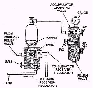
SERVO ACCUMULATOR.- The servo accumulator (fig. 6-8) maintains a reserve of servo pressure to meet peak demands for both the train and elevation power drives. Servo pressure enters the accumulator through a spring-loaded check valve,
Figure 6-7.-Auxiliary relief valve block (power-off brake released).
Figure 6-8.-Servo accumulator (schematic diagram), UV84. Valve UV84 prevents accumulator pressure from feeding back through the pump during shutdown. Fluid then ports to the accumulator flask and to the receiver-regulator of each power drive. The fluid reserve in the flask is held under pressure by the nitrogen charged bladder, THE MK 75 76MM POSITIONING EQUIPMENT The Mk 75 uses two 3-kW low-inertia dc motors and reduction gearing for train and a single 4.5-kW dc motor and reduction gearing for elevation. This system was discussed in detail in chapter 5. |
||
|
||