Custom Search
|
|
 
|
||
|
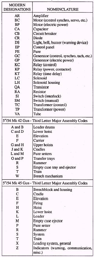
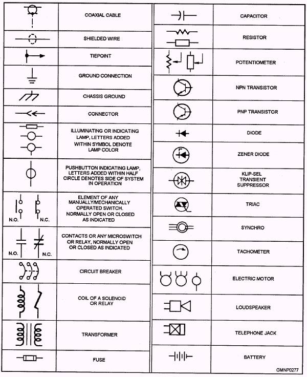
ELECTRICAL SYMBOLS AND REFERENCE DESIGNATIONS The symbols presently used to designate electrical/ electronic parts and assemblies in NAVSEA drawings are specified in ANSI Y32.2-1975, Graphic Symbols for Electrical and Electronics Diagrams. This publication provides alternate methods for symbolizing certain parts and should be consulted when a symbol is not clearly understood. The electrical/electronic schematic print section of your systems maintenance manual will normally provide a description of the symbols used. Figure 5-15 shows the electrical symbols used in the reference drawings of gun mounts currently in service. In some modem gun mounts and GMLSs, other than standard reference designations may be used for parts peculiar to a particular system. In this event, the manufacturer assigns reference designation letters and numbers. Normally, the designations used by each manufacturer are published in the OP for that particular gun mount. In general, the electrical components or devices used in a modem gun mount or GMLS (the 5"/54 Mk 45 or Mk 13 Mod 4) are identified by a combination of letters and numbers or groups of letters and numbers. Table 5-1 is a partial listing of first- and second-group designation used on the Mk 45 gun mount. The first two letters identify a specific type of component. The third letter identifies the major equipment assembly within which the component is located. The number that follows the third letter indicates the number of the Table 5-1.-Electrical Component Designations
Figure 5-15.-Electrical symbols. device within the assembly. For example, SIH1 is an interlock switch (SI) used in the left upper hoist(H) and the number 1 distinguishes this particular switch from all other switches in the hoist. As is often the case, there is one modem gun mount (76-mm 62-caliber Mk 75) in which both the electrical symbols and designations are not all consistent with other gun mounts. For example, a relay is designated with a number followed by the letter K, followed by another number (1K1, 2K1, and soon). The symbol for a relay is a rectangular box. |
 |
|
|
||