Custom Search
|
|
 
|
||
|
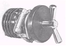
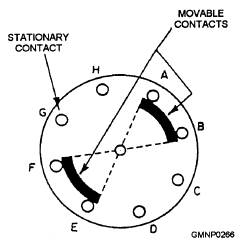
ROTARY SWITCHES.- A rotary switch can take the place of several switches. As the knob or handle of a rotary switch is rotated, it opens one circuit and closes another. This action can be seen from an examination of figure 5-3. Most rotary switches have numerous layers called wafers or pancake sections. By adding wafers, the switch can be made to operate as a large number of switches. Rotary switches are used in gun mount equipment to select modes of operation and for many other functions. J Rotary Switch.- The J rotary switch (fig. 5-3) consists of an equal number of rotors and pancake sections. The number of sections required in the switch is determined by the application. A shaft with an operating handle extends through the center of the rotors. The movable contacts are mounted on the rotors, and the stationary contacts are mounted on the pancake sections. Each section consists of eight stationary contacts, designated A through H, and a rotor with two insulated movable contacts spaced 180 degrees apart. Figure 5-4 shows the contact array for all pancake sections. Each movable contact is arranged to bridge two adjacent stationary contacts. The switch has eight positions. A detente mechanism properly aligns the contacts in each position of the operating handle. In one position, the rotor contacts bridge segments A-B and E-F; in the next position, the rotor contacts bridge segments B-C and F-G. Diagonally opposite pairs of contacts are subsequently bridged for the remaining positions. The various circuit leads are connected to the proper pancake terminals. To transfer circuits, you just turn the handle. JR Rotary Switch.- The letters JR are the designation for a family of rotary switches. These switches (fig. 5-5), by a single motion, control a number
Figure 5-3.-The J multipole rotary switch.
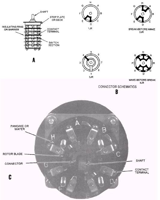
Figure 5-4.-The J switch contact arrangement. of switches called pancakes or wafers located on the same shaft. To achieve this control, the switch is built in layers, or wafers, along the shaft of the switch handle (fig. 5-5, view A). The number of contacts determines the type of switching circuit. Usually all the wafers in the JR switches are identical; that is, they may be all make-before-break or break-beforemake (fig. 5-5, view B). Each wafer is in itself a separate switch (fig. 5-5, view C). Make-before-break means that as the switch is rotated the rotor contacts touch the next J pole before breaking the previous contact. Break-before-make means that as the, switch is rotated the rotor contacts leave the original pole before the movable contacts touch the new pole, In rare cases you may find a switch containing both types of switching arrangements. Extra wafers are provided for use as spares. As the handle of the switch is turned, the rotor blades in all wafers turn simultaneously to make and break the circuits. A detente wheel is incorporated in each switch assembly to ensure proper positioning. Also, a stop plate (fig. 5-5, view A) limits the rotation of the switch by means of a stop pin. The pin is fixed in the stop plate to prevent overtravel. The JR switch is smaller and more readily disassembled than the J switch. These two features save space and facilitate repairs. The JR switch is classified as a 1JR, 2JR, 3JR, or 4JR type. • The 1JR switch has only one movable contact per section. This movable contact bridges two adjacent stationary contacts. • The 2JR switch is the same electrically as the J switch and is the type used for general ordnance applications. The 2JR switch has two movable
Figure 5-5.-JR rotary switch: A. Typical switch arrangement, schematic; B. JR switch contact arrangement; C. Face view. contacts per section, 180 degrees apart. Each used for selecting one of several (up to seven) movable contact bridges two adjacent stationary inputs. contacts. • The 4JR switch has two movable contacts in • The 3JR switch uses one of the stationary each wafer. The movable contacts bridge contacts as a common terminal. This three adjacent stationary contacts. stationary contact is connected, in turn, to each of the other stationary contacts of the The JR switch is stacked in multiples of five section by a single wiper contact. The 3JR is sections (up to 25 sections). In some cases, a switch with a number of sections that are not a multiple of 5 has been installed. If this switch must be replaced, a switch with the next largest number of sections that is a multiple of 5 should be installed if space permits. All sections of a switch should be the same; but, if absolutely necessary, a switch with some sections of one type and some sections of another type can be provided. The JR switches are rated at 115 volts, 60 Hz, and 10 amperes. The switch should not be used on dc circuits because of the possibility of severely burned contacts when operated slowly (teased). Barriers are also provided between sections to prevent terminals from turning and shorting to adjacent terminals. If the sections are not uniform, the switch will be designated JRSP, followed by the number of sections. The stop deck on the JR switch (fig. 5-5, view A) permits setting the switch to the number of positions desired. By inserting pins or screws in the stop deck immediately after the desired last position, you can keep the switch from moving beyond that point. |
 |
|
|
||