| Tweet |

Custom Search
|
|
 
|
||
|
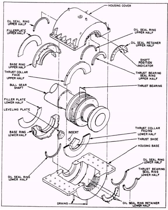
MAIN THRUST BEARING CLEARANCE MEASUREMENTS As you have already learned in Gas Turbine Systems Technician (Electrical) 3/ Gas Turbine Systems Technician (Mechanical) 3, volume 1, NAVEDTRA 10563, propeller thrust is transferred from each propulsion shaft to the hull through a Kingsbury main thrust bearing (fig. 3-6). The Kingsbury thrust bearing uses the wedge-shaped oil film lubrication principle. This principle is based on an oil film between two sliding surfaces tends to assume a tapered depth with the thicker film at the entering side. In a Kingsbury assembly, eight bearing shoes are installed on each side of the thrust collar. Therefore, eight separate wedge-shaped oil films are installed on each thrust face. Since the bearing shoes are free to tilt slightly, the oil automatically assumes the taper required by shaft speed, loading, and oil viscosity. The main thrust bearing assembly consists of the bearing housing, two thrust rings, and a thrust collar. The housing, thrust rings, and thrust collar facings are all split horizontally. Each thrust ring is made up of 8 steel thrust shoes with tin babbitt facings, 16 leveling plates, and a retainer ring. The thrust collar has a two-piece removable steel thrust face attached to each side. Each thrust shoe contains a hardened shoe support with a spherical face. The support bears on the upper leveling plate and the spherical face allow the thrust shoe to pivot or tilt slightly in all directions. This arrangement allows the bearing to operate on the free-wedge film lubrication principle. One thrust shoe on each side is fitted with a resistance temperature element (RTE). Due to the spring isolation system, main thrust bearing clearance measurements are no longer taken with a depth micrometer. All measurements are now taken with a dial indicator that measures the deflection of the propulsion shaft at the main flange. There are two methods (static and dynamic) used to create shaft deflection. The method used depends on the ship class. The static method must be used on CG-66 and above and all DDG-51 class ships. The dynamic method is
Figure 3-6.- Thrust bearing and housing. used for all other gas turbine-powered ships. Take a brief look at these two methods to measure main thrust bearing clearances. Static Method In the static method, a dial indicator is mounted on top of the aft end of the thrust housing with the zero pointer against the forward face of the first shaft flange aft of the thrust bearing. While the controllable and reversible pitch (CRP) system is operating, the propeller pitch is advanced to 100 percent ahead with the local controls at the oil distribution (OD) box. The electric CRP pump is then secured, and the hub servo bottomed-out by use of the emergency pitch hand pump. The reduction gear is then rocked with the turning gear motor by use of the ratchet wrench to turn the motor. This movement assures that the shaft is bottomed-out on the ahead thrust collar. If the clearance is within normal limits, and no abnormal conditions exist, log the readings and put the system back in service. If the clearance is not within normal limits, or a noticeable increase or decrease is measured, inspect the thrust bearing. Check for any abnormal rendition (scored or wiped shoes) and take corrective action as necessary. NOTE Approximately six to eight turns of the wrench in either direction will remove the backlash; turn an additional two to four turns. Repeat once or twice in each direction with 2500 to 3000 psi on the emergency hand pump. |
||
|
||
|
|
Integrated Publishing, Inc. - A (SDVOSB) Service Disabled Veteran Owned Small Business
|