| Tweet |

Custom Search
|
|
 
|
||
|
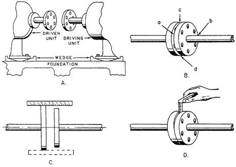
ALIGNMENT OF SHAFT AND COUPLING When you install or assemble pumps driven by electric motors, make sure the unit is aligned properly. If the shaft is misaligned, you must realign the unit to prevent shaft breakage and damage to bearings, pump casing wearing rings, and throat bushings. Always check the shaft alignment with all the piping in place. Some driving units are connected to the pump by a FLEXIBLE COUPLING. A flexible coupling
Figure 9-15.-Grid-type flexible coupling. (fig 9-15) is intended to take care of only a slight misalignment. Misalignment should never exceed the amount specified by the pump manufacturer. If the misalignment is excessive, the coupling parts are subjected to severe punishment, necessitating frequent replacement of pins, bushings, and bearings. It is absolutely necessary to have the rotating shafts of the driver and driven units in proper alignment. Figure 9-16 shows coupling alignment. You should check the shaft alignment when the pump is opened for repair or maintenance, or if a noticeable vibration occurs. You must realign the unit if the shafts are out of line or inclined at an angle to each other. Whenever practicable, check the alignment with all piping in place and with the adjacent tanks and piping filled. When the driving unit is connected to the pump by a FLANGE COUPLING, the shafting may require frequent realignment, which may be indicated by high temperatures, noises, and worn bearings or bushings. Wedges, or shims, are sometimes placed under the bases of both the driven and driving units (fig 9-16 view A) for ease in alignment when the machinery is installed. When the wedges or other packing have been adjusted so the outside diameters and faces of the coupling flanges run true as they are manually revolved, the chocks are fastened, the units are securely bolted to the foundation, and the coupling flanges are bolted together. The faces of the coupling flanges should be checked at 90-degree intervals. This method is shown in figure 9-16 view B. Find the distances between the faces at point a, point b (on the
Figure 9-16.-Coupling alignment.
opposite side), point c, and point d (opposite point c). This action will show whether the coupling faces are parallel to each other. If they are not parallel to each other, adjust the driving unit or the pump with shims until the couplings check true. While measuring the distances, you must keep the outside diameters of the coupling flanges in line. To do this, place the scale across the two flanges, as shown in figure 9-16 view C. If the flanges do not line up, raise or lower one of the units with shims, or shift them sideways. The procedure for using a thickness gauge to check alignments is similar to that for a scale. When the outside diameters of the coupling flanges are not the same, use a scale on the surface of the larger flange, and then use a thickness gauge between the surface of the smaller flange and the edge of the scale. When the space is narrow, check the distance between the coupling flanges with a thickness gauge, as shown in figure 9-16 view D. Check wider spaces with a piece of square key stock and a thickness gauge. |
||
|
||