| Tweet |

Custom Search
|
|
 
|
||
|
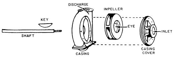
CLASSIFICATION OF PUMPS Pumps aboard ship outnumber all other auxiliary machinery units. They include such types as centrifugal, rotary, and jet pumps. In the following section we discuss these different pumps and their application to the engineering plant. Centrifugal Pumps Aboard gas turbine ships, centrifugal pumps of various sizes are driven by electric motors to move different types of liquid. The fire pump and seawater service pump are two examples of this type of pump. A basic centrifugal pump has an impeller keyed to a drive shaft, which is rotated by an electric motor. The drive shaft is fitted inside a casing, which has a suction inlet and a discharge
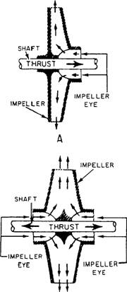
Figure 9-1.-Centrifugal pump. outlet. Figure 9-1 shows the arrangement of components in a centrifugal pump. CENTRIFUGAL PUMP CLASSIFICATION.Centrifugal pumps may be classified in several ways. For example, they may be either single-stage or multistage. A single-stage pump has only one impeller; a multistage pump has two or more impellers housed together in one casing. In a multistage pump, each impeller usually acts separately, discharging to the suction of the nextstage impeller. Centrifugal pumps are also classified as horizontal or vertical, depending on the position of the pump shaft. Impellers used in centrifugal pumps may be classified as single-suction or double-suction, depending on the way in which liquid enters the eye of the impeller. Figure 9-2 shows singlesuction and double-suction arrangements of centrifugal pump impellers. The single-suction impeller (view A) allows liquid to enter the eye from one side only; the double-suction impeller (view B) allows liquid to enter the eye from both sides. The double-suction arrangement has the advantage of balancing the end thrust in one direction with the end thrust in the other direction. Impellers are also classified as CLOSED or OPEN. A closed impeller has side walls that extend from the eye to the outer edge of the vane tips; an open impeller does not have side walls. Most centrifugal pumps used in the Navy have closed impellers. CONSTRUCTION.- As a rule, the casing for the liquid end of a pump with a single-suction impeller is made with an end plate that can be removed for inspection and repair of the pump. A pump with a double-suction impeller is generally made so one-half of the casing may be lifted without disturbing the pump. Since an impeller rotates at high speed, it must be carefully machined to minimize friction. An impeller must be balanced to avoid vibration. A close radial clearance must be maintained between
Figure 9-2.-Centrifugal pump impellers. A. Single-suction. B. Double-suction. the outer hub of the impeller and that part of the pump casing in which the hub rotates. The purpose of this is to minimize leakage from the discharge side of the pump casing to the suction side. Because of the high rotational speed of the impeller and the necessarily close clearance, the rubbing surfaces of both the impeller hub and the casing at that point are subject to stress, causing rapid wear. To eliminate the need for replacing an entire impeller and pump casing solely because of wear in this location, most centrifugal pumps are designed with replaceable casing wearing rings. In most centrifugal pumps, the shaft is fitted with a replaceable sleeve. The advantage of using a sleeve is that it can be replaced more economically than the entire shaft. Mechanical seals and stuffing boxes are used to seal between the shaft and the casing. Most pumps are now furnished with mechanical seals; mechanical seals do not result in better pump operation; but, they do provide a better environment, keep bilges dry, and preserve the liquid being pumped. Seal piping (liquid seal) is installed to cool the mechanical seal. Most pumps in saltwater service with total head of 30 psi or more are also fitted with cyclone separators. These separators use centrifugal force to prevent abrasive material (such as sand in the saawater) from passing between the sealing surfaces of the mechanical seal. There is an opening at each end of the separator. The opening at the top is for "clean" water, which is directed though tubing to the mechanical seals in the pump. The high-velocity "dirty" water is directed through the bottom of the separator, back to the inlet piping for the pump.
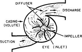
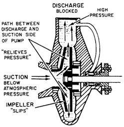
Figure 9-3.-Centrifugal pump flow. Bearings support the weight of the impeller and shaft and maintain the position of the impeller-both radially and axially. Some bearings are grease-lubricated with grease cups to allow for periodic relubrication. The power end of the centrifugal pump you are to work with has an electric motor that is maintained by your ship's Electrician's Mate. OPERATION.- Liquid enters the rotating impeller on the suction side of the casing and enters the eye of the impeller (fig 9-3). Liquid is thrown out through the opening around the edge of the impeller and against the side of the casing by centrifugal force. This is where the pump got its name. When liquid is thrown out to the edge of the casing, a region of low pressure (below atmospheric) is created around the center of the impeller; more liquid moves into the eye to replace the liquid that was thrown out. Liquid moves into the center of the impeller with a high velocity (speed). Therefore, liquid in the center of the impeller has a low pressure, but it is moving at a high velocity. Liquid moving between the blades of the impeller spreads out, which causes the liquid to slow down. (Its velocity decreases.) At the same time, as the liquid moves closer to the edge of the casing, the pressure of the liquid increases. This change (from low pressure and high velocity at the center to high pressure and low velocity at the edge) is caused by the shape of the opening between the impeller blades. This space has the shape of a diffuser, a device that causes the velocity-pressure relationship of any fluid that moves through it to change. A centrifugal pump is considered to be a nonpositive-displacement pump because the volume of liquid discharged from the pump changes whenever the pressure head changes. The pressure head is the combined effect of liquid weight, fluid friction, and obstruction to flow. In a centrifugal pump, the force of the discharge pressure of the pump must be able to overcome the force of the pressure head; otherwise, the pump could not deliver any liquid to a piping system. The pressure head and the discharge pressure of a centrifugal pump oppose each other. When the pressure head increases, the discharge pressure of the pump must also increase. Since no energy can be lost, when the discharge pressure of the pump increases, the velocity of flow must decrease. On the other hand, when the pressure head decreases, the volume of liquid discharged from the pump increases. As a general rule, a
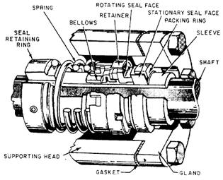
Figure 9-4.-Nonpositive-displacement pump. centrifugal pump is usually located below the liquid being pumped. (NOTE: This discussion assumes a constant impeller speed.) Figure 9-4 shows that when the pump discharge is blocked, nothing happens because the impeller is hollow. A tremendous buildup in pressure cannot occur because the passages in the impeller (between the discharge and suction side of the pump) act like a built-in relief valve. When the discharge pressure and pressure head are equal (as in this case), the impeller is allowed to rotate (slips) through the liquid in the casing. NOTE: Centrifugal pumps used for intermittent service may have to run for long periods of time against a blocked discharge. Friction between the impeller and the liquid raises the temperature of the liquid in the casing and causes the pump to overheat. To prevent this, a small line is connected between the discharge and the suction piping of the pump. When a centrifugal pump is started, the vent line must be opened to release entrained air. The open passage through the impeller of a centrifugal pump also causes another problem. It's possible for liquid to flow backwards (reverse flow) through the pump. A reverse flow, from the discharge back to the suction, can happen when the pressure head overcomes the discharge pressure of the pump. A reverse flow can also occur when the pump isn't running and another pump is delivering liquid to the same piping system. To prevent a reverse flow of liquid through a centrifugal pump, a check valve is usually installed in the discharge line. NOTE: Instead of two separate valves, some installations use a globe stop-check valve. With a check valve in the discharge line, whenever the pressure above the disk rises above the pressure below it, the check valve shuts. This prevents liquid from flowing backwards through the pump. MAINTENANCE.- You must observe the operation and safety precautions pertaining to pumps by following the EOP subsystem of the EOSS-if your ship has EOSS. If not, use the Naval Ships' Technical Manual (NSTM) and/or the instructions posted on or near each individual pump. You must follow the manufacturer's technical manual or MRCs for PMS-related work for all maintenance work. The MRCS list in detail what you have to do for each individual maintenance requirement. Mechanical Seals.- Mechanical seals are rapidly replacing conventional packing as the means of controlling leakage on centrifugal pumps. Pumps fitted with mechanical seals eliminate the problem of excessive stuffing box leakage, which can result in pump and motor bearing failures and motor winding failures. Where mechanical shaft seals are used, the design ensures that positive liquid pressure is supplied to the seal faces under all conditions of operation and that there is adequate circulation of the liquid at the seal faces to minimize the deposit of foreign matter on the seal parts. One type of mechanical seal is shown in figure 9-5 Spring pressure keeps the rotating seal face
Figure 9-5.-Type-1 mechanical seal.
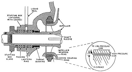
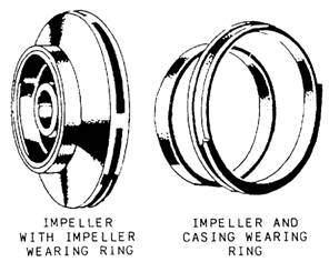
Figure 9-6.-Stuffing box on a centrifugal pump. snug against the stationary seal face. The rotating seal and all of the assembly below it are affixed to the pump shaft. The stationary seal face is held stationary by the seal gland and packing ring. A static seal is formed between the two seal faces and the sleeve. System pressure within the pump assists the spring in keeping the rotating seal face tight against the stationary seal face. The type of material used for the seal face depends on the service of the pump. When a seal wears out, it is simply replaced. You should observe the following precautions when performing maintenance on mechanical seals: Do not touch new seals on the sealing face because body acid and grease can cause the seal face to prematurely pit and fail. Replace mechanical seals when the seal is removed for any reason or when the leakage rate cannot be tolerated. Position mechanical shaft seals on the shaft by stub or step sleeves. Shaft sleeves are chamfered (beveled) on outboard ends to provide ease of mechanical seal mounting. Do not position mechanical shaft seals by using setscrews. Fire pumps and all seawater pumps installed in surface ships are being provided with mechanical shaft seals with cyclone separators. The glands are designed to incorporate two or more rings of packing if the mechanical shaft seal fails. A water flinger is fitted on the shaft outboard of the stuffing box glands to prevent leakage from the stuffing box following along the shaft and entering the bearing housings. They must fit tightly on the shaft. If the flingers are fitted on the shaft sleeves instead of on the shaft, ensure that no water leaks under the sleeves. Stuffing Box Packing.- Although most centrifugal pumps on gas turbine ships have mechanical seals, you should be familiar with stuffing box packing. The packing in centrifugal pump stuffing boxes (fig 9-6) is renewed following the PMS. When replacing packing, be sure to use packing of the specified material and the correct size. Stagger the joints in the packing rings so they fall at different points around the shaft. Pack the stuffing box loosely and set up lightly on the gland, allowing a liberal leakage. With the pump in operation, tighten the glands and gradually compress the packing. It is important to do this gradually and evenly to avoid excessive friction. Uneven tightening could cause overheating and possible scoring of the shaft or the shaft sleeve. On some centrifugal pumps, a lantern ring is inserted between the rings of the packing. When repacking stuffing boxes on such pumps, be sure to replace the packing beyond the lantern ring. The packing should not block off the liquid seal line connection to the lantern ring after the gland has been tightened. Figure 9-6 shows how the packing is arranged. Notice how the lantern ring lines up with the liquid seal connection when the gland is tightened. Renewing Shaft Sleeves.- In some pumps the shaft sleeve is pressed onto the shaft tightly by a hydraulic press. In this case, the old sleeve must be machined off with a lathe before a new one can be installed. On others, the shaft sleeve may have a snug slip-on fit, butted up against a shoulder on the shaft and held securely in place with a nut. On smaller pumps, new sleeves can be installed by removing the water end casing, impeller, and old shaft sleeves. New sleeves are carried as repair parts; they can also be made in the machine shop. On a large pump, the sleeve is usually pressed on; the old sleeve must be machined off before a new one can be pressed on. You must disassemble the pump and take the sleeve to a machine shop, a repair shop, or a naval shipyard to have this done. To prevent water leakage between the shaft and the sleeve, some sleeves are packed, others have an O-ring between the shaft and the abutting shoulder. For detailed information, consult the appropriate manufacturer's technical manual or applicable blueprint. Renewing Wearing Rings.- The clearance between the impeller and the casing wearing ring (fig, 9-7) must be maintained as directed by the manufacturer. When clearances exceed the specified amount, the casing wearing ring must be replaced. On most ships, this job can be done
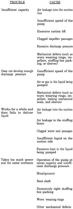
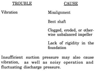
Figure 9-7.-Impeller, impeller wearing ring, and casing wearing ring for a centrifugal pump. by the ship's force, but it requires the complete disassembly of the pump. All necessary information on disassembly of the unit, dimensions of the wearing rings, and reassembly of the pump is specified by PMS or can be found in the manufacturer's technical manual. Failure to replace the casing wearing ring when the allowable clearance is exceeded results in a decrease of pump capacity and efficiency. If a pump has to be disassembled because of some internal trouble, the wearing ring should be checked for clearance. Measure the outside diameter of the impeller hub with an outside micrometer and the inside diameter of the casing wearing ring with an inside micrometer; the difference between the two diameters is the actual wearing ring diametric clearance. By checking the actual wearing ring clearance with the maximum allowable clearance, you can decide whether to renew the ring before reassembling the pump. The applicable MRCS area readily available source of information on proper clearances. Wearing rings for most small pumps are carried aboard ship as part of the ship's repair parts allowance. These may need only a slight amount of machining before they can be installed. For some pumps, spare rotors are carried aboard ship. The new rotor can be installed and the old rotor sent to a repair activity for overhaul. Overhauling a rotor includes renewing the wearing rings, bearings, and shaft sleeve. Operating Troubles.- You will be responsible for the maintenance of centrifugal pumps. The following table is a description of some of the problems you will have to deal with together with the probable causes:
|
||
|
||