| Tweet |

Custom Search
|
|
 
|
||
|
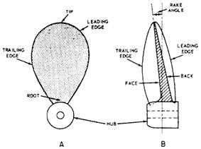
PROPELLER The screw-type propeller consists of a hub and blades all spaced at equal angles about the axis. When the blades are integral with the hub, the propeller is known as a solid propeller. When the blades are separately cast and secured to the hub with studs, the propeller is known as a built-up propeller. Some of the parts of the screw propeller are identified in figure 8-9. The face (or pressure face) is the afterside of the blade when the ship is moving ahead. The back (or suction back) is the surface opposite the face. As the propeller rotates, the face of the blade increases pressure on the
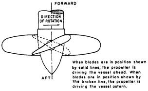
Figure 8-9.-Propeller blade. water to move it in a positive astern movement. The overall thrust, or reaction force ahead, comes from the increased water velocity moving astern. The tip of the blade is the most distant from the hub. The root of the blade is the area where the blade joins the hub. The leading edge is the edge that first cuts the water when the ship is going ahead. The trailing edge (also called the following edge) is opposite the leading edge. A rake angle exists when the tip of the propeller blade is not precisely perpendicular to the axis (hub). The angle is formed by the distance between where the tip really is (forward or aft) and where the tip would be if it were in a perpendicular position. A screw propeller may be broadly classified as either fixed pitch or controllable pitch. The pitch of a fixed-pitch propeller cannot be altered during operation. The pitch of a controllable-pitch propeller can be changed at any time, subject to bridge or engine-room control. The controllablepitch propeller can reverse the direction of a ship without requiring a change of direction of the drive shaft. The blades are mounted so that each one can swivel or turn on a shaft that is mounted in the hub (as shown in figure. 8-10) SUMMARY This chapter has provided you with some basic information on several types of propulsion systems used on Navy ships. You should become familiar with the propulsion system on your ship. Keep in mind, the propulsion systems are usually a little different from ship to ship.
Figure 8-10.-Schematic diagram of a controllable-pitch propeller. |
||
|
||